Installation manual
HB-37420-810-01-25F-EN PSC1-C-100 Installation manual - V2.2.docx Page 18 of 201
Version: 25F
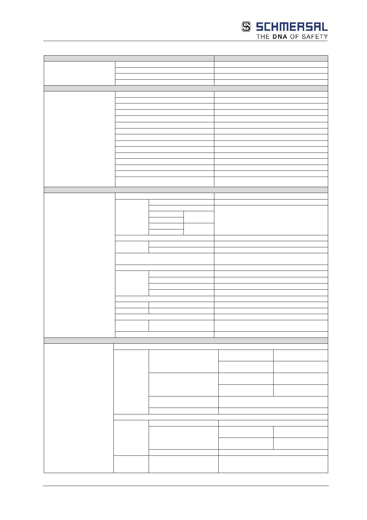
3.7.1.1.1 Tech. characteristic data PSC1-C-100 (-FBx
(1)
)
related characteristic data
PL according to EN ISO 13849
-9
SIL according to IEC 61508
20 years = max. service life
Max. number of expansion modules
Interface for expansion modules
bus connector, can be plugged into DIN rail
Number of safe digital inputs
Number of safe digital outputs
pn switching** or 2
pp switching ** 4
Number of safe digital I/O
Number of relay outputs (1-channel)
2
Number of safe analogue inputs
Removable screw terminals
(D-Sub / screw terminal)
Encoder technology
(See table Encoder
specifications)
-
Supply voltage
(tolerance)
24 VDC; 2A
(-15%, +20%)
Fuse
min. 30 VDC; max. 10A
bypassed
bypassed
Max. power consumption (logic)
(1)
Rated data digital inputs 24 VDC/ 20 mA, type 1 according to ISO 61131-
Rated data digital outputs
pn switching 24 VDC/2 A ***
pp switching 24 VDC/2 A ***
Signal outputs 24 VDC; 250mA
Pulse outputs
24 VDC; 250mA
NO DC13
24 VDC/ 2 A
Rated data analogue inputs
Electrical data (only for UL)
Rated data digital outputs
pn switching Temperature rating
24 VDC; 2A (G.P.)
Temperature rating
24 VDC; 1.8A (G.P.)
pp switching Temperature rating
24 VDC; 2A (G.P.)
Temperature rating
24 VDC; 1.8A (G.P.)
Max. cumulative current (pn
8A
Auxiliary outputs 24 VDC; 250mA (G.P.)
5 - 9, 15 - 19 Temperature rating
24 VDC; 2A (G.P.)
Temperature rating
24 VDC; 1.8A (G.P.)
Max. cumulative current I/O
Rated data
relay
Normally open contact
24 VDC; 2A (Pilot Duty)