6.16.4 Redundancy status and overview
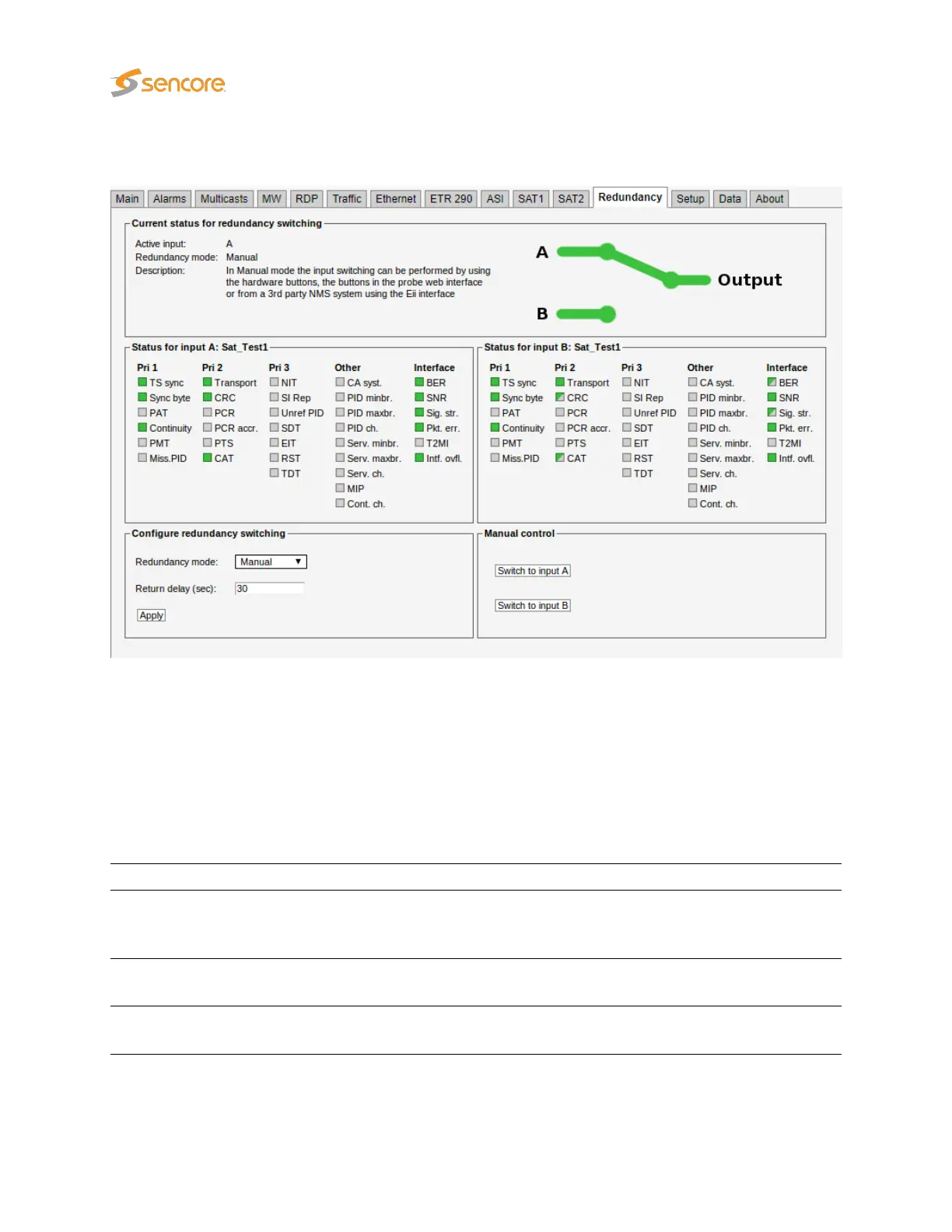
The Redundancy tab GUI will provide a simple overview of the status on both input signals, which ETR
alarms and redundancy options that is enabled, and which redundancy mode is enabled.
6.16.5 Redundancy modes
The probe has three different redundancy modes giving the operator different levels of control. When a
physical button is pushed the GUI will be overridden.
Redundancy modes:
SuperLocal:
When a physical signal button is pressed on the device the signal will be switched
to the specified signal. The GUI will also be overridden and set in a SuperLocal
redundancy mode. It is also possible to set the mode to SuperLocal when in the GUI.
Manual:
The operator may alter the output by pressing the GUI buttons defined in the manual
control area. This may also be done by using 3rd party NMS systems.
Auto:
The probe itself will determine the output based on the specified thresholds alarm
status for each input signal.
220 VB2xx GigE User’s Manual version 5.4