4.8 The Hardware Modules and Connectors (VB220)
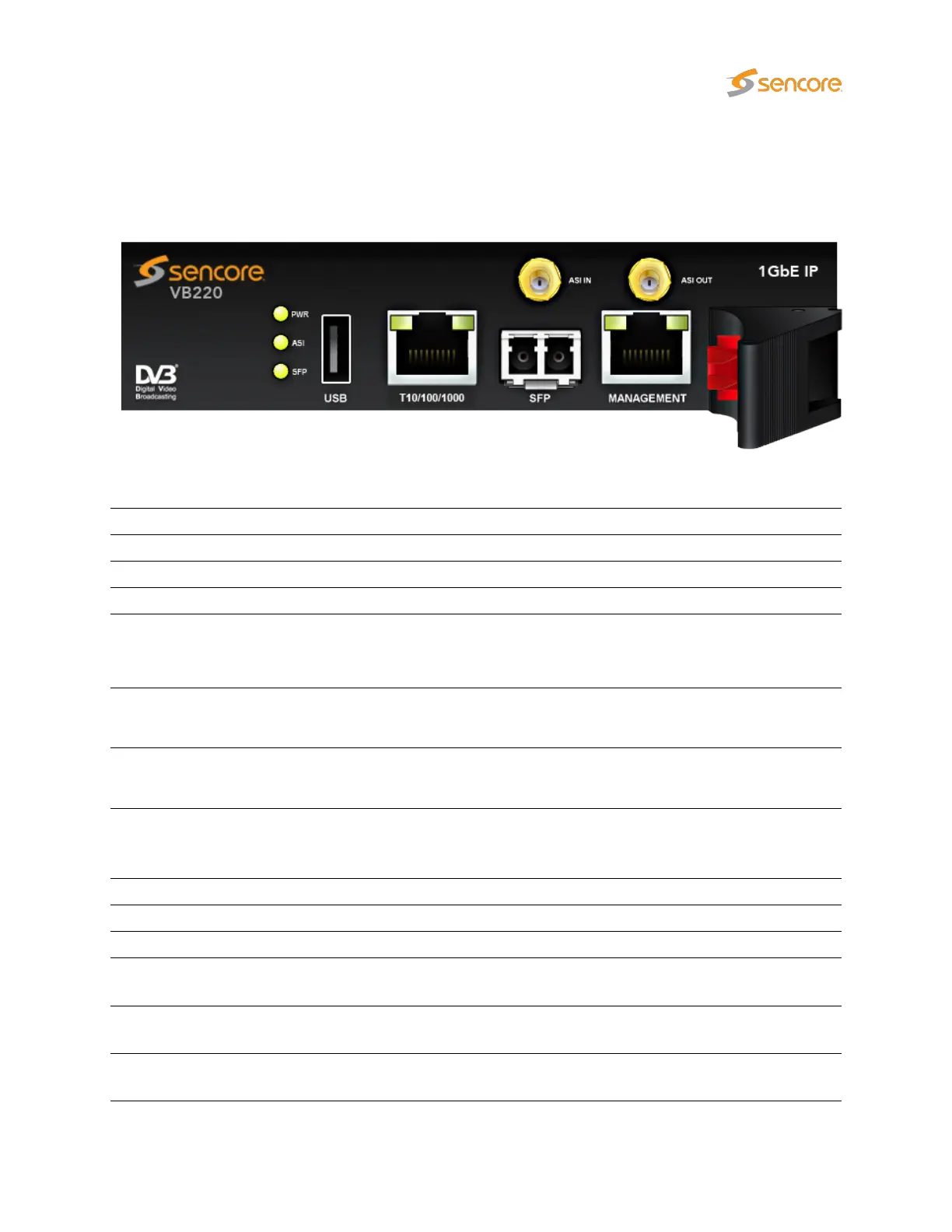
4.8.1 The Probe Module
The Probe module is equipped with the following connectors:
USB: USB serial port emulator for initial set-up of the probe – Type A
1PPS: 1PPS reference clock input – 50 ohm BNC female
ASI IN: ASI transport stream input – 75 ohm HD-BNC female
ASI OUT: ASI transport stream output – 75 ohm HD-BNC female
10/100/1000T:
(eth0)
For monitoring a 10/100/1000 Mbit/s electrical/copper signal – RJ-45. The probe
can only monitor either the SFP input signal OR the 10/100/1000T input signal
(selected from software), unless licensed to use both inputs.
MANAGEMENT:
(eth1)
For management of the probe on a separate network – RJ-45. This interface
supports 10/100/1000T.
SFP:
(eth2)
For monitoring a 1000 Mbit/s signal with a small form-factor pluggable – SFP.
Used when connecting to optical networks.
The coloring of LEDs serve the following purposes:
POWER: Green indicates power.
ASI: Green indicates ASI sync.
SFP LINK: Green indicates that SFP link is up and operational.
SFP ACT:
Green indicates that the SFP is receiving a signal. Blinking indicates a problem
with auto-negotiation; if SFP LINK is dark, check cables and SFP types.
10/100/1000T:
Green indicates link. Yellow indicates that the interface is receiving data (RX).
Both LEDs are off if input is taken from the SFP module.
MANAGEMENT:
Green indicates link with 1000 Mbit/s speed. Yellow indicates link with 100 Mbit/s
speed. Otherwise the speed is 10Mbit/s.
VB2xx GigE User’s Manual version 5.4 25