4
Installation
Terminal assignment
Operating Instructions – MOVIDRIVE
®
modular
127
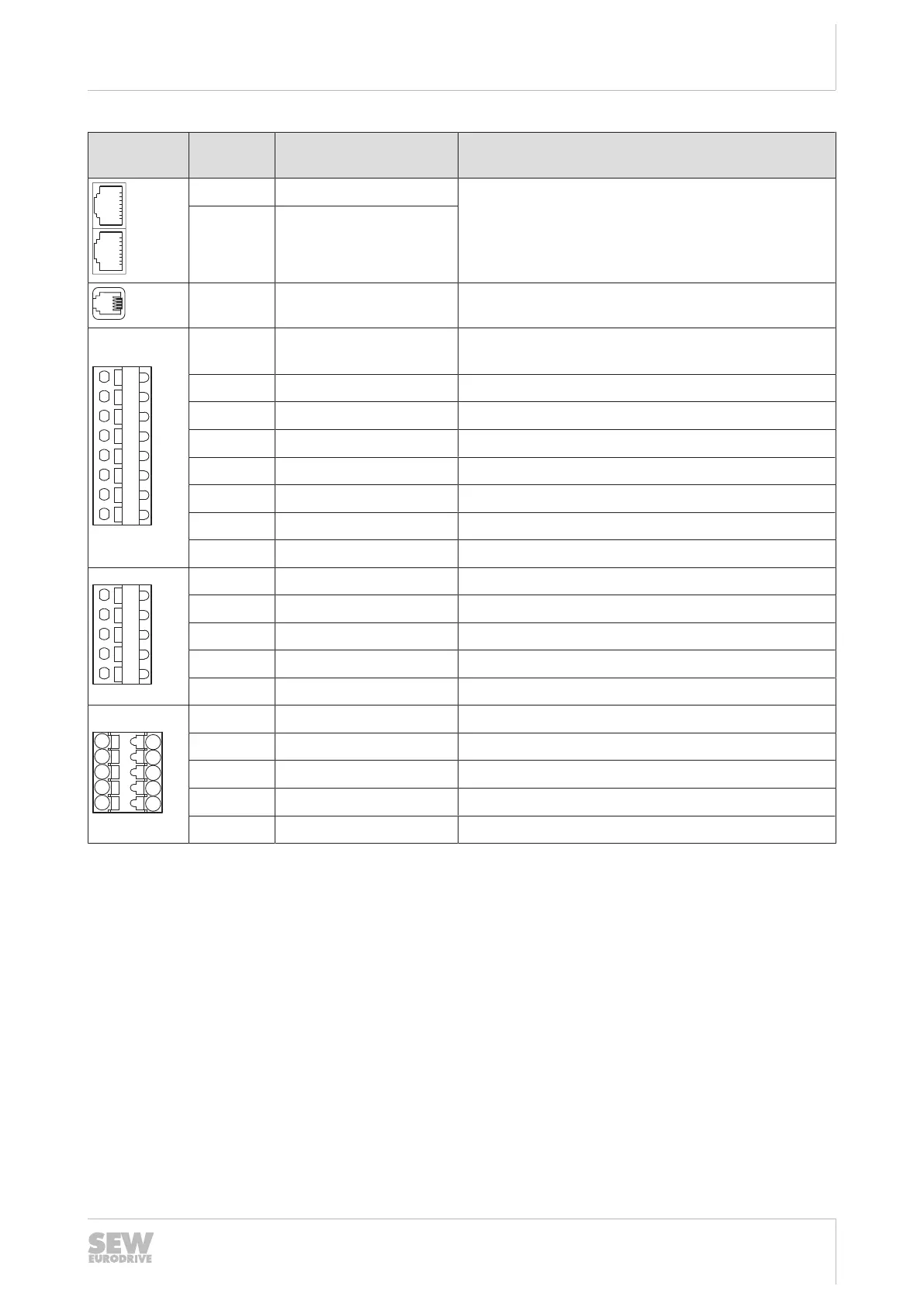
Representa-
tion
Terminal Connection Short description
X30 OUT
System bus
X30 IN
X31 SEW‑EURODRIVE Service interface
X20:1 DI00 Digital input 1, with fixed assignment "Output stage
enable"
X20:2 DI01 Digital input 2, freely programmable
X20:3 DI02 Digital input 3, freely programmable
X20:4 DI03 Digital input 4, freely programmable
X20:5 DI04 Digital input 5, freely programmable
X20:6 DI05 Digital input 6, freely programmable
X20:7 GND Reference potential
X20:8 +24V DC 24V voltage output
X21:1 DO00 Digital output 1, freely programmable
X21:2 DO01 Digital output 2, freely programmable
X21:3 DO02 Digital output 3, freely programmable
X21:4 DO03 Digital output 4, freely programmable
X21:5 GND Reference potential
X6:1 F_STO_P1 DC +24 V input F_STO_P1
X6:2 F_STO_M DC 0 V input F_STO_M
X6:3 F_STO_P2 DC +24 V input F_STO_P2
X6:4 GND Reference potential
X6:5 24V STO_OUT V
out
= DC 24V supply of F_STO_P1 and F_STO_P2
24748536/EN – 11/2017
 Loading...