Chapter 5: Assembly and Disassembly of Parts
SPD-M20A Service Manual
23
3) Remove the screw (tapping, M3x10) fixing the leak sensor, and remove the
leak sensor.
4) After replacing the leak sensor, attach the hinge that was removed, and adjust
the position (5.1.3 Front Panel Adjustment Procedure).
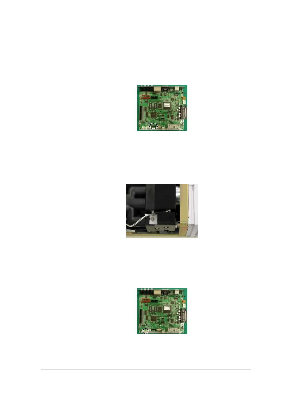
<Micro SW ASSY>
1) Remove the micro SW connector connected to the CPU board
Micro SW connector
2) Remove the screw (P3 M2x12) fixing the microswitch, and remove the micro
SW.
5.1.4.3 Thermistor (thermistor ASSY P/N 228-42522-91)
1) Prior to removing the thermistor, it necessary to remove the sponge.
Loosen the screw (sems, M4x8), and remove the sponge with the plate.
Sponge
NOTE
The screw fixing the sponge (plate) also tightens the guide fin for the W lamp
housing underneath, and should not be removed.
2) Remove the thermistor connector connected to the CPU board.
Thermistor connector
3) Remove the screw (sems, P3 M3x6) fixing the thermistor, and detach it.
<Temperature controlled cell connector>
 Loading...