Chapter 6: Maintenance and Adjustments
SPD-M20A Service Manual
44
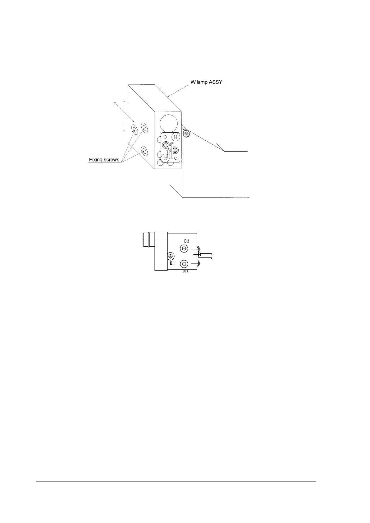
3) Loosen the 3 W lamp ASSY fixing screws, and adjust the W lamp ASSY so that the
center of the light image is positioned as near as possible at the center of the target cell
mark.
4) Tighten the fixing screws with a torque of approximately 0.6 Nm, tightening them is the
order of "B1->B2->B3", as indicated in the figure below.
5) Remove the target cell, and install the water-filled flow cell.
6.3.5 Mirror 2 Adjustment (back and forth direction)
1) Set the variable slit of the slit ASSY to the 1.2 nm side.
The driving part is on the bottom at this state.
2) Move the slit ASSY in the Y - Y' direction shown in the figure below and confirm the
position where the light spot on the slit is the smallest.
3) Loosen the elevation angle adjustment screws on the M2 ASSY and adjust the mirror of
the M2 in the back and forth direction so that the light spot on the slit is the smallest
when the slit ASSY is pressed in the Y direction shown in the figure below.
For example, the position confirmed in step 2) and the position where the slit ASSY is
pressed in the Y direction is 1 mm away from each other, move the mirror of the M2
1 mm closer to the slit ASSY.
4) Loosen the slit ASSY fixing screws and remove the slit ASSY.
Do not pull out the connector.
 Loading...