EasyManuals Logo

Shimadzu SPD-M20A User Manual

Shimadzu SPD-M20A
108 pages
To Next Page IconTo Next Page
To Previous Page IconTo Previous Page
Page #27 background imageLoading...
Page #27 background image
Chapter 5: Assembly and Disassembly of Parts
SPD-M20A Service Manual
25
5.2 Printed circuit board
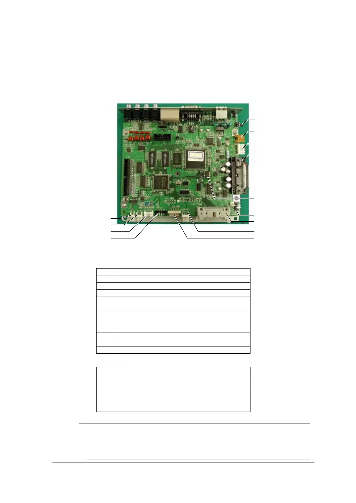
<PCB ASSY, PDA-CPU >
Each part of the CPU board is shown below.
CPU board ASSY
Connector connection assignments
No.
Connection assignment
1
Lamp fan
2
Thermistor
3
Panel (LED)
4
Door sensor (micro SW)
5
Slit drive motor
6
Slit photo sensor (HP)
7
PDA ASSY
8
Rear panel fan
9
Power unit
10
Temperature controlled cell
11
Leak sensor
Name and function of each part
Name
Function
ST TEST
Turns the lamp on or off manually, as during
adjustment
(see 6.2.4 ).
EEPROM
Records settings.
When replacing CPU board, it is necessary to insert it
onto the new board.
NOTE
The EEPROM is not included on the replacement boards (board, PDA-CPU P/N
228-41823-91).
Transfer the EEPROM on the old board to the new board.
1
2
3
4
6
8
7
11
10
9
EEPROM
ST TEST
5

Table of Contents

Questions and Answers:

Question and Answer IconNeed help?

Do you have a question about the Shimadzu SPD-M20A and is the answer not in the manual?

Shimadzu SPD-M20A Specifications

General IconGeneral
BrandShimadzu
ModelSPD-M20A
CategorySecurity Sensors
LanguageEnglish

Related product manuals