Chapter 5: Assembly and Disassembly of Parts
SPD-M20A Service Manual
26
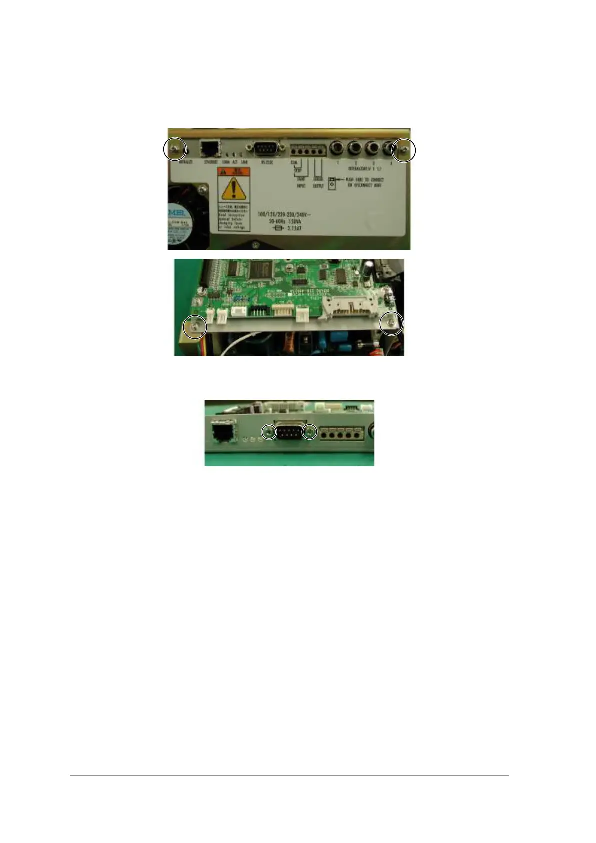
1) Remove the connector connected to the CPU board.
2) Remove the screw (sems, P3 M3x6) fixing the CPU board from the rear panel and
inside, and detach the CPU board together with the plate.
Positions of CPU Board ASSY Fixing Screws
3) Remove the spacer bolts to the left and right of the RS-232C connector.
Positions of RS-232C Connector Fixing Bolts
4) Remove the four screws (sems, P3 M3x6) fixing the CPU board to the plate,
and remove the CPU board.
 Loading...