Chapter 6: Maintenance and Adjustments
SPD-M20A Service Manual
50
If the emission line is at 64 ele to 72 ele, move the 0 order light to the right.
(Moving the 0 order light by 0.05 mm moves the emission light by 1 ele.)
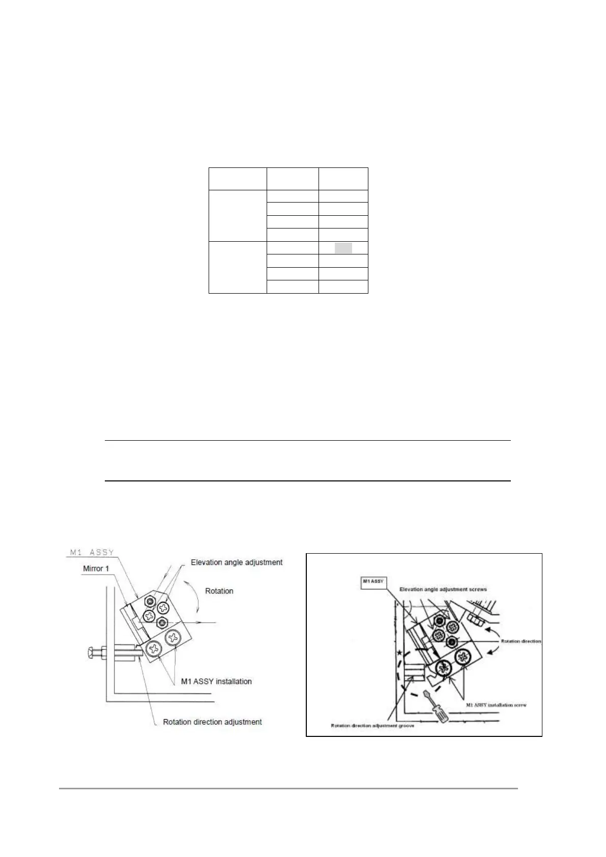
< Measures when FAIL is displayed during wavelength check using the mercury
lamp >
If the 253.7 nm emission line of the 8 nm slit shown in the table above is off to the negative
direction, finely adjust the M1 ASSY by the procedure described below.
1) View the instrument from the front and turn the left side elevation angle adjustment
screw on the M1 ASSY (see the figure below) clockwise or the right side screw
counterclockwise by 10 to 20 degrees.
2) Perform wavelength calibration again and then wavelength check Hg. All the 8 nm slit
values will be shifted slightly in the positive direction. Use this method for fine adjustment.
NOTE
If the mask M1-L is off to the front, it may cause wavelength gap. Make sure that it is
positioned at the correct position.
*Type dose not have a groove in the base. *Type there is a groove in the base