Chapter 6: Maintenance and Adjustments
SPD-M20A Service Manual
47
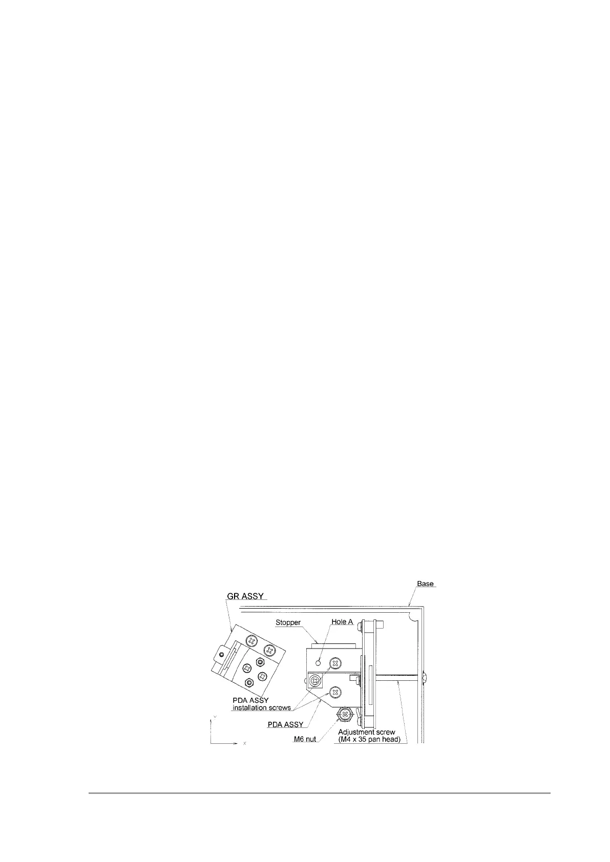
6.3.9 Photodiode Array (PDA) Adjustment (Rough Adjustment)
In this adjustment, loosen the adjustment screw while checking the Hg spectrum on the
monitor screen, move the PDA ASSY in the X direction shown in the figure below, and
search for the focal position.
For this adjustment, select PDA Utility [Optical Check] and use [Measure Bandwidth].
1) While the PDA ASSY is pressed against the stopper, fasten the PDA ASSY installation
screws.
2) Attach the adjustment screw.
3) Temporarily fix the screw at the position where hole A of the PDA ASSY is 2 to 3 mm
closer to the GR ASSY from the corresponding position on the base.
4) Fix the guide plate contacting the side face of the PDA ASSY.
5) Loosen the PDA ASSY installation screws by approximately 30 degrees from the fully
tightened position.
6) Connect the optical system, controller, and PC and turn ON the power switch.
7) Start the Optical Check software from PDA Utility.
8) Change the scale from wavelength to element and set the element axis to 40 ele to
90 ele.
9) Display the 254 nm reference line.
10) Mount the Hg jig (P/N 228-34179-91).
Keep the Hg lamp OFF.
11) Press the [Dark] button to measure the dark level.
12) Light up the Hg lamp.
13) Press the [Spectrum] key to display the 253.7 nm emission line.
14) Move the PDA ASSY in the X direction using the adjustment screw and fix the PDA
ASSY at the position where the half bandwidth of the emission line becomes 1.18 ele
max.
15) Adjust the position of the emission line peak within a range 60 ele to 63 ele (maximum
adjustment range: 52 ele to 72 ele).
 Loading...