Chapter 5: Assembly and Disassembly of Parts
SPD-M20A Service Manual
31
1) If the connector attached to the PDA ASSY has not been removed, then remove
it.
2) Remove the screw (sems, M2x5) fixing the slit ASSY, and remove the slit ASSY.
Positions of Slit ASSY Fixing Screws
3) To adjust after installation, see 6.5 Slit Adjustment.
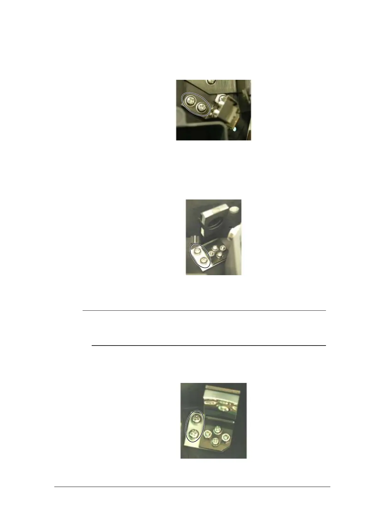
<Mirror M1 ASSY>
1) Remove the two screws (sems, P4 M4x8) fixing the M1 ASSY, and remove the
M1 ASSY.
Positions of M1 Fixing Screws
2) To adjust after installation, see 6.3 Mirror 1 Adjustment.
NOTE
The fixing plates for the M1 ASSY and M2 ASSY are identical, so note the fixing
positions when removing both simultaneously.
The mirror with a mask attached to the mirror is the M1 ASSY.
< Mirror M2 ASSY>
1) Remove the two screws (sems, P4 M4x8) fixing the M2 ASSY, and remove the
M2 ASSY.
Positions of M2 Fixing Screws
2) To adjust after installation, see 6.4 Mirror 2 Adjustment.