Chapter 6: Maintenance and Adjustments
SPD-M20A Service Manual
42
Since this calibration method is used, the optical axis needs to be adjusted so that images at each
wavelength are symmetric and have only a small amount of warp. If not, wavelength calibration
cannot be performed properly and wavelengths may not match precisely in either slit.
6.3.2 Optical Axis Adjustment Procedure
Span adjustment values created from 656 nm light and 360 nm light are shared on the 1.2 nm and
8 nm slits. Therefore, the wavelength at 254 nm, which is far from 656 nm, is less precise in some
optical axis adjustment conditions. Especially at the 8 nm slit, the light spot on the slit is large and the
light intensity distribution tends to vary. In this condition, adjustment of the position of the image on
the slit is important. When performing optical axis adjustment, start with mirror 1 and roughly adjust
the PDA element so that PDA utility can be started. Then, perform fine adjustment while checking the
width and symmetry of the emission line displayed on the screen. See the following section for
specific adjustment procedures.
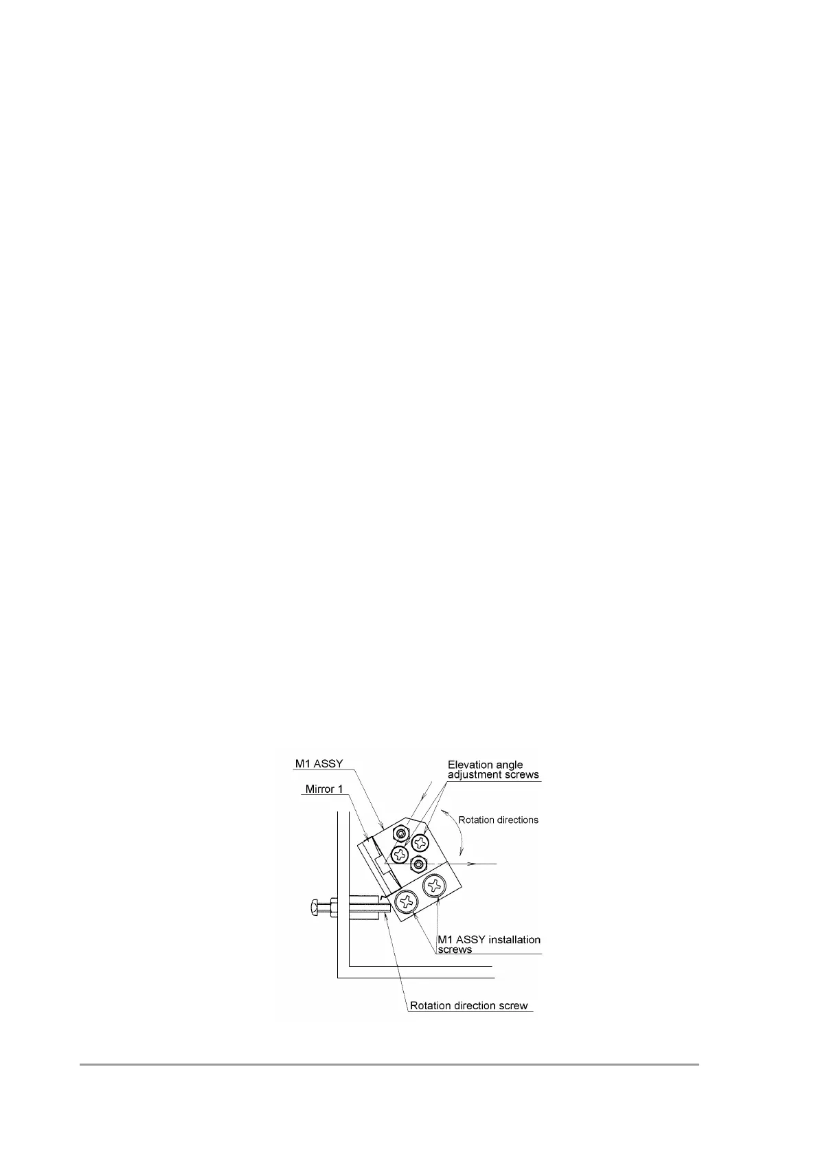
6.3.3 Mirror 1 Adjustment
Remove the Cover of Optical Unit
1) Light the D2 lamp.
2) Install the target cell (P/N 228-34181-91).
3) Slightly loosen the M1 ASSY installation screws.
Adjustment method is different depending on shape of the base of M1 ASSY below.
Please adjust sure.
*Type dose not have a groove in the base.
4) Adjust the light image so that is on the center point of the target cell mark using the
rotation direction adjustment screw and elevation angle adjustment screws.
5) Tighten the M1 ASSY installation screws.
6) Loosen the rotation direction adjustment screw.
7) Tighten the nut on the rotation direction adjustment screw.