Operating Instructions Chapter 5
M4000 Adv., Adv. A/P, Area
8010797/PA53/27-06-05 © SICK AG • Industrial Safety Systems • Germany • All rights reserved
31
Mounting
Under the authority of OSHA and ANSI the safety distance as specified by
ANSI B11.19@1990 E.4.2.3.3.5 and Code of Federal Regulations, Volume 29,
Part 1910.217 … (h) (9) (v) depends on:
• stopping/run-down time of the machine or system
(The stopping/run-down time is shown in the machine documentation or must be
determined by taking a measurement.)
• response time of the protective device (response times see chapter 11.1 “Data sheet”
on page 73)
• reach or approach speed
• other parameters that are stipulated by the standard depending on the application
Calculation of the safety distance for perpendicular approach
How to calculate the safety distance S according to EN 999 and EN 294:
The following calculation shows an example calculation of the safety distance. Depending
on the application and the ambient conditions, a different calculation may be necessary.
First, calculate S using the following formula:
S = 1600 × T + C [mm]
Where …
T = Stopping/run-down time of the machine
+ Response time of the M4000 system after light path interruption [s]
S = Safety distance [mm]
C = Supplement [mm], depending on the number of beams (1, 2, 3 or 4), see Tab. 13
Number of beams 1 2 3 4
Recommended height of
the beams above the floor
[mm]
750 400
900
300
700
1100
300
600
900
1200
C [mm] 1200 850 850 850
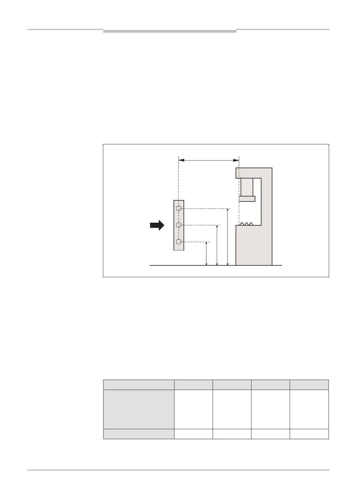
Fig. 16: Safety distance to
the hazardous point for
perpendicular approach
Note
height of the beams above
the floor
s
dous
point
approach
Height of the beams above the floor
AUDIN - 7 bis rue de Tinqueux - 51100 Reims - France - Tel : 03.26.04.20.21 - Fax : 03.26.04.28.20 - Web : http: www.audin.fr - Email : info@audin.fr

 Loading...


