Safety Circuit / Restart Lock (STO)
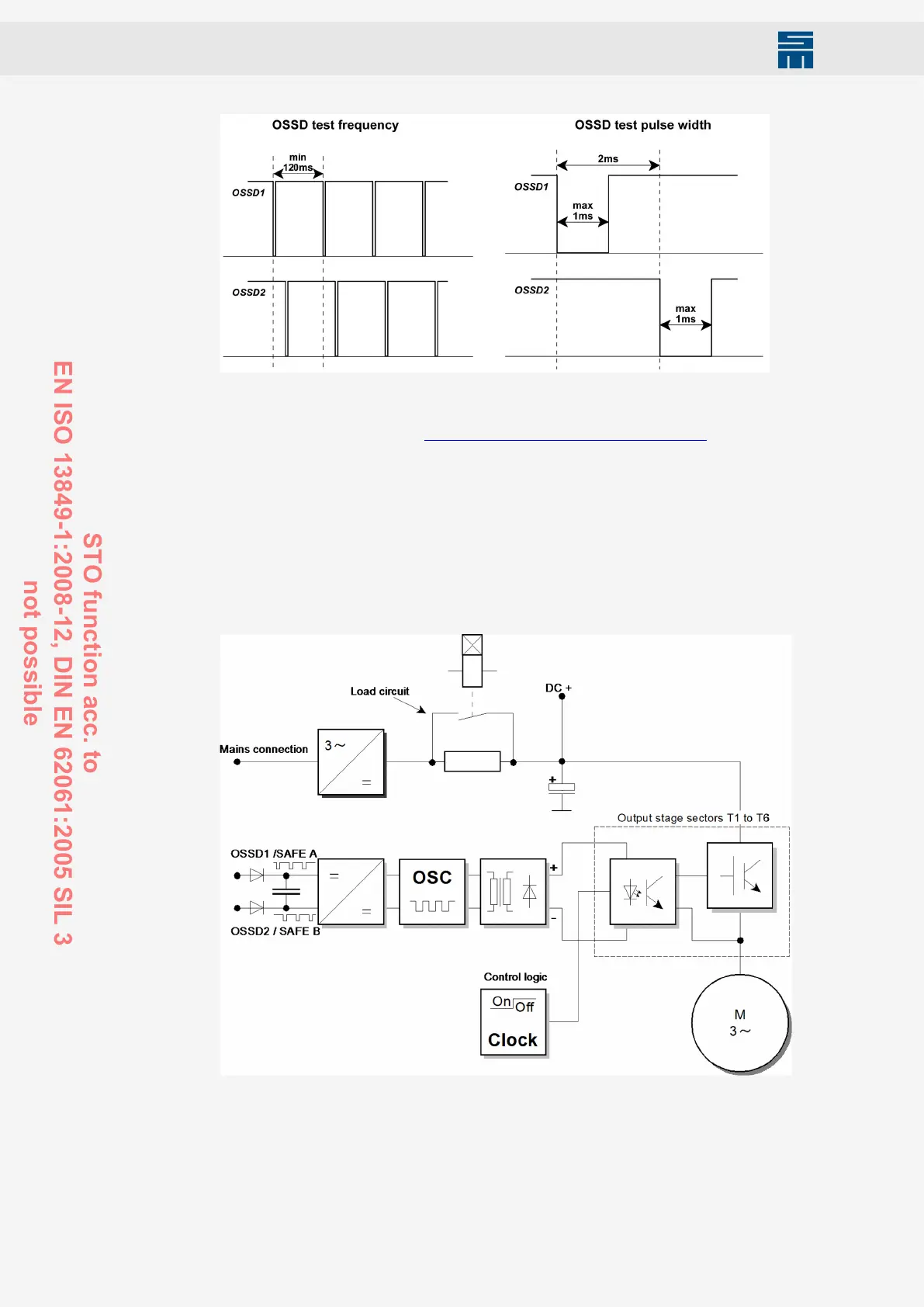
Fig. 55: OSSD signals
Fig. 55: OSSD signals
The safety circuit is controlled by the OSSD1+2 signal or via one or several emergency
stop switch devices. see also chapter 12.2 “Wiring Example”, page 103.
If the OSSD signals or at least one of the +24 V conductors fail, the safety circuit switch-
es the pulse pattern of the output stage control sectors off. The response time of the
restart lock is max. 4 ms.
The restart lock must only be controlled when
▶ the drive is at a secure standstill (stop category 2),
▶ the higher-ranking control has deactivated the drive module,
▶ (reference speed value 0)
▶ the holding brake of the motor has been arrested.
Fig. 56: Safety circuit control
Fig. 56: Safety circuit control
102 Drive System SD2M - Hardware Description 036228xxF
STO function acc. to
EN ISO 13849-1:2008-12, DIN EN 62061:2005 SIL 3
not possible