Connection Examples
I
´
1
1
R
2
ext
1
Rint
+
1
1
680 W
1
4400 W
+
=
8 mA
´
=
4.71 V
Sensor on:
Middle voltage of the sensor: (4.71 V + 2.36 V ) / 2 = 3.54 V
Middle voltage of the input IN8 at the SD2M: (5.9 V + 5.4 V ) / 2 = 5.65 V
The voltage level must be increased according to the difference between the middle volt-
ages. This is done by a boost voltage at R
1
.
Boost voltage R
1
: 5.65 V - 3.54 V = 2.11 V
Resistance R
1
: (24 V / 2.11 V) × 588 Ω = 6.688 kΩ → 6.8 kΩ
(588 Ω results from the resistances of R
2
external and Rinternal.)
Note
If you use other sensors, please pay attention to the input switching thresholds of the
sensor and the data sheet provided by the spindle manufacturer.
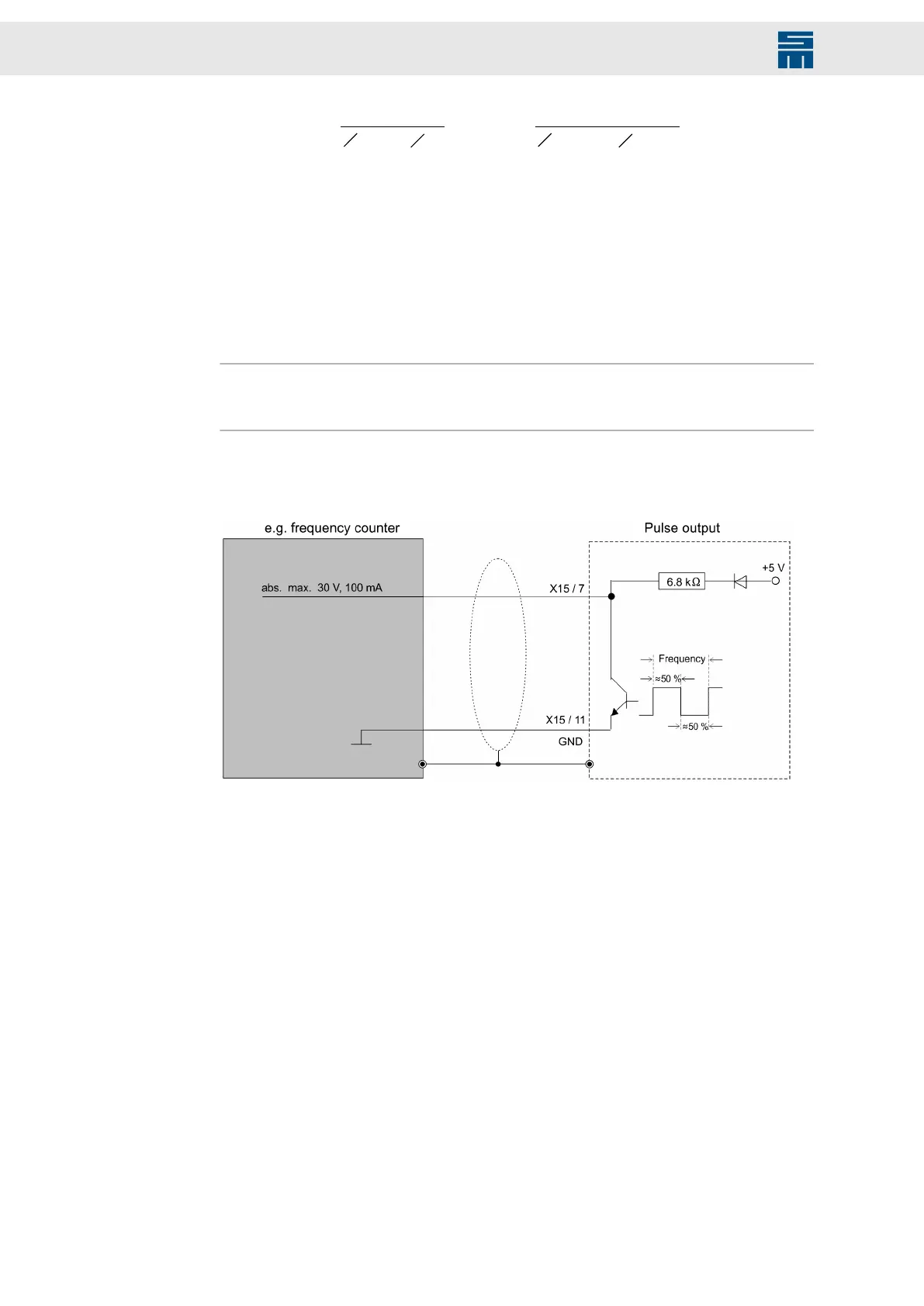
8.5.5 PULSE (Speed Pulses)
Fig. 28: PULSE − speed pulses
Fig. 28: PULSE − speed pulses
66 Drive System SD2M - Hardware Description 036228xxF