Connection Examples
8.3 X7 – Encoder Emulation
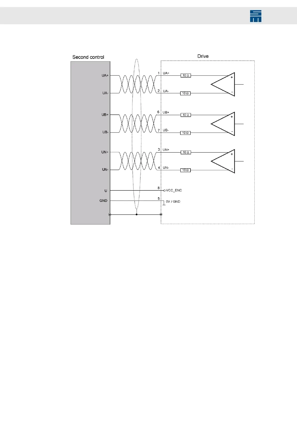
Fig. 21: Encoder Emulation
Fig. 21: Encoder Emulation
The transmission meets the requirements of the standard TIA/EIA-422-B with a voltage
differential of at least. ±0.9 V.
62 Drive System SD2M - Hardware Description 036228xxF