Connector Pin Assignment
7.10 X18– Analog Interface
The available functions of the analog inputs and outputs are different depending on the
drive function. You can set the desired function in the software drivemaster2.
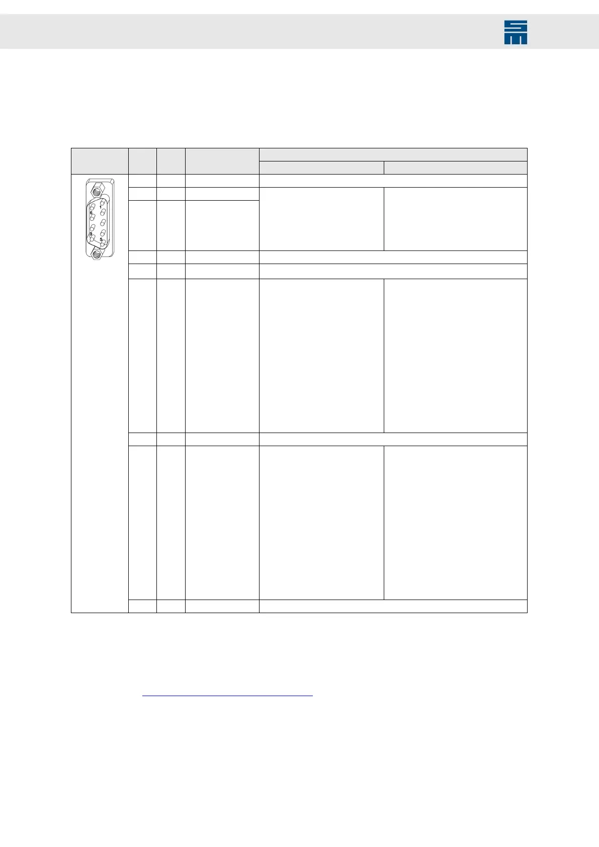
9-pole male submin D connector
Configurable functionsX18 Pin I/O Name
SERVO / VECTOR (SVC) VF
1 I AIN1- Reference point of AIN1+ (pin 2)
2 I AIN1+
3 I
AIN0+
(1)
▶ No function
▶ Speed reference value
▶ Current reference value
▶ Current limitation
▶ W24 – Warning threshold
’current'
▶ No function
▶ Speed reference value
▶ Current limitation
▶ W24 – Warning threshold ’current'
4 I/O GND Ground
5 n.c.
6 O AOUT1 ▶ No function
▶ Target speed
▶ Speed reference value
▶ Speed actual value
▶ Speed error
▶ Current reference value
▶ Current actual value
▶ Motor temperature
▶ Power output stage tempera-
ture
▶ Motor load
▶ Power output stage load
▶ Voltage of the bus
▶ Active power
▶ DC link current Idc
▶ No function
▶ Target speed
▶ Speed reference value
▶ Speed actual value
▶ Speed error
▶ Current reference value
▶ Current actual value
▶ Motor temperature
▶ Power output stage temperature
▶ Motor load
▶ Power output stage load
▶ Voltage of the bus
▶ Active power
▶ DC link current Idc
7 I AIN0- Reference point for AIN0+ (pin 3)
8 O AOUT0 ▶ No function
▶ Target speed
▶ Speed reference value
▶ Speed actual value
▶ Speed error
▶ Current reference value
▶ Current actual value
▶ Motor temperature
▶ Power output stage tempera-
ture
▶ Motor load
▶ Power output stage load
▶ Voltage of the bus
▶ Active power
▶ DC link current Idc
▶ No function
▶ Target speed
▶ Speed reference value
▶ Speed actual value
▶ Speed error
▶ Current reference value
▶ Current actual value
▶ Motor temperature
▶ Power output stage temperature
▶ Motor load
▶ Power output stage load
▶ Voltage of the bus
▶ Active power
▶ DC link current Idc
9 O VCC_10 10 V supply voltage
(1)
The analog input AIN0+ (reference to ground) is also provided at connector X16/ pin 10.
Locking bolts flange: max. tightening torque = 0.7 Nm
Related topics
X18 – Analog Inputs/Outputs, page 80
54 Drive System SD2M - Hardware Description 036228xxF