DANGER
No torque when restart lock is active
The motor cannot provide a torque when the restart lock is activated. Thus
non-self-locking drives could be released.
→ Non-self-locking drives as hanging loads must be blocked with a me-
chanical brake.
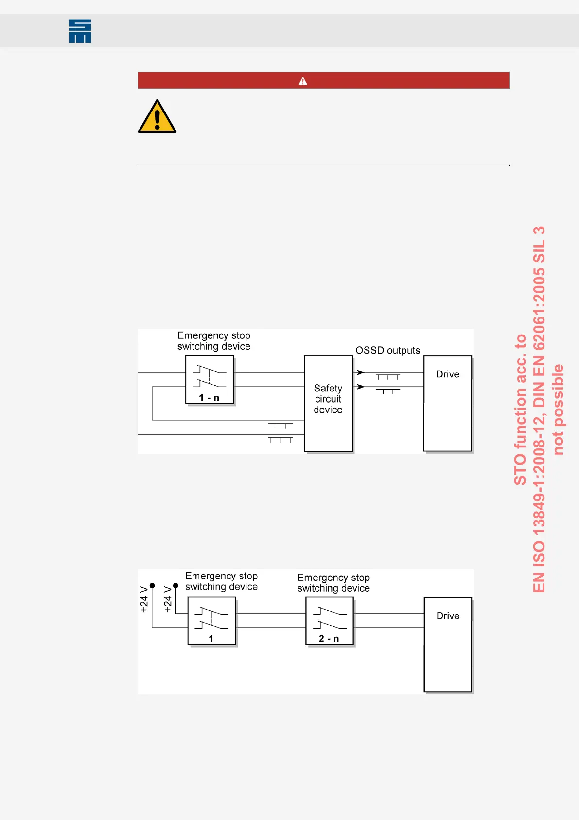
12.2 Wiring Example
Combining a safe emergency stop command device with an OSSD safety relay or a light
barrier with OSSD outputs and the safe switching off of the pulse patterns allows the cre-
ation of an error detection circuit, which achieves a safe stop (according to stop func-
tion category 0+1) according to the safety requirements of SIL 3 (EN ISO 13849-1). This
circuit allows connecting several emergency stop devices in parallel, which are perma-
nently monitored.
Circuit with OSSD (SIL 3)
Fig. 57: Wiring with OSSD
Fig. 57: Wiring with OSSD
Circuit without OSSD (SIL 3)
The following figure shows a circuit without OSSD safety device, whilst only safety di-
rected command devices with forcibly opened contacts in two-channel design are used.
SIL 3 (according to EN ISO 13849-1) is achieved. It is also possible to cascade sever-
al different safe emergency stop devices, position switches or door locks to one safety
circuit.
Fig. 58: Wiring without OSSD
Fig. 58: Wiring without OSSD
103Drive System SD2M - Hardware Description 036228xxF
Safety Circuit / Restart Lock (STO)
STO function acc. to
EN ISO 13849-1:2008-12, DIN EN 62061:2005 SIL 3
not possible