Connector Pin Assignment
7.5 X10 – Safety (STO)
WARNING
STO function acc. to EN ISO 13849-1:2008-12, DIN EN 62061:2005
SIL 3 not possible
→ For more information refer to chapter 12 “Safety Circuit / Restart Lock
(STO)”, page 100.
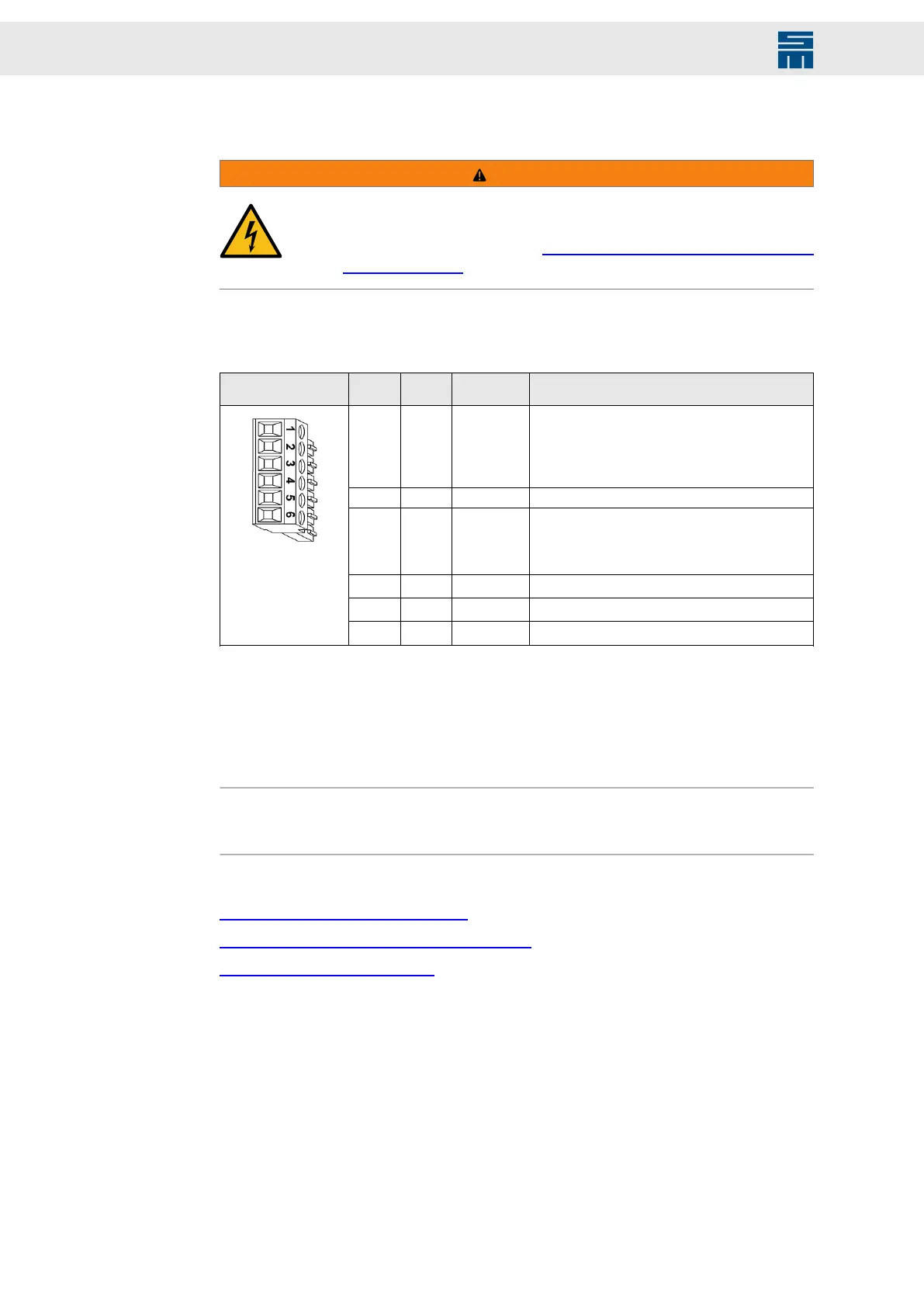
Safety circuit and restart lock (STO)
6-pole Mini-Combicon connector, suitable for mating connector MC 1.5/ 6-ST-3.81
(Phoenix)
Mating con-
nector X10
Pin I/O Name Meaning
1 I SAFEA /
OSSD1
Enable of the safety circuit
▶ Continuous load at 24 V > 160 mA/24 V, de-
pendent on the device performance
▶ Startup peak current per device can exceed
8 A/24 V during the first 2 ms.
2 – GND Reference potential
3 I SAFEB /
OSSD2
Enable of the safety circuit
▶ Permanent load approx. 15 mA/24 V
▶ Startup peak current is negligible under nor-
mal conditions.
4 n.c.
5 n.c.
6 O
24 V
(1)
Logic voltage 18 to 28 volts (uncontrolled)
(1)
The 24 V output is not suited to supply external safety circuits because an external voltage source is
necessary to comply with the applicable standards. If the safety function (STO) is not required, this voltage
is only used to bridge the pins 1 and 3.
Specification of terminal connections
▶ Conductor cross-section solid/stranded: 0.14 to 1.5 mm²
▶ Tightening torque: 0.22 to 0.25 Nm
Note
The power supply unit is only activated when SAFEA and SAFEB are connected. If the
safety function (STO) is not required, pin 1 and pin 3 must be bridged to pin 6.
Related topics
X10 – Safety Circuit (STO), page 63
Safety Circuit / Restart Lock (STO), page 100
Connection Diagram, page 111
46 Drive System SD2M - Hardware Description 036228xxF