Drive Amplifier SD2M
5.9 Connectors
This section describes the position of the connectors.
▶ For detailed information on every connector refer to chapter 7 “Connector Pin As-
signment”, page 44.
▶ For examples on connector wiring refer to chapter 8 “Connection Examples”,
page 60.
▶ For examples on the complete device wiring refer to chapter C “Connection Dia-
gram”, page 111.
Note
You can order the suitable connector kit for the device series SD2M under the article
number 322099601 at SIEB & MEYER.
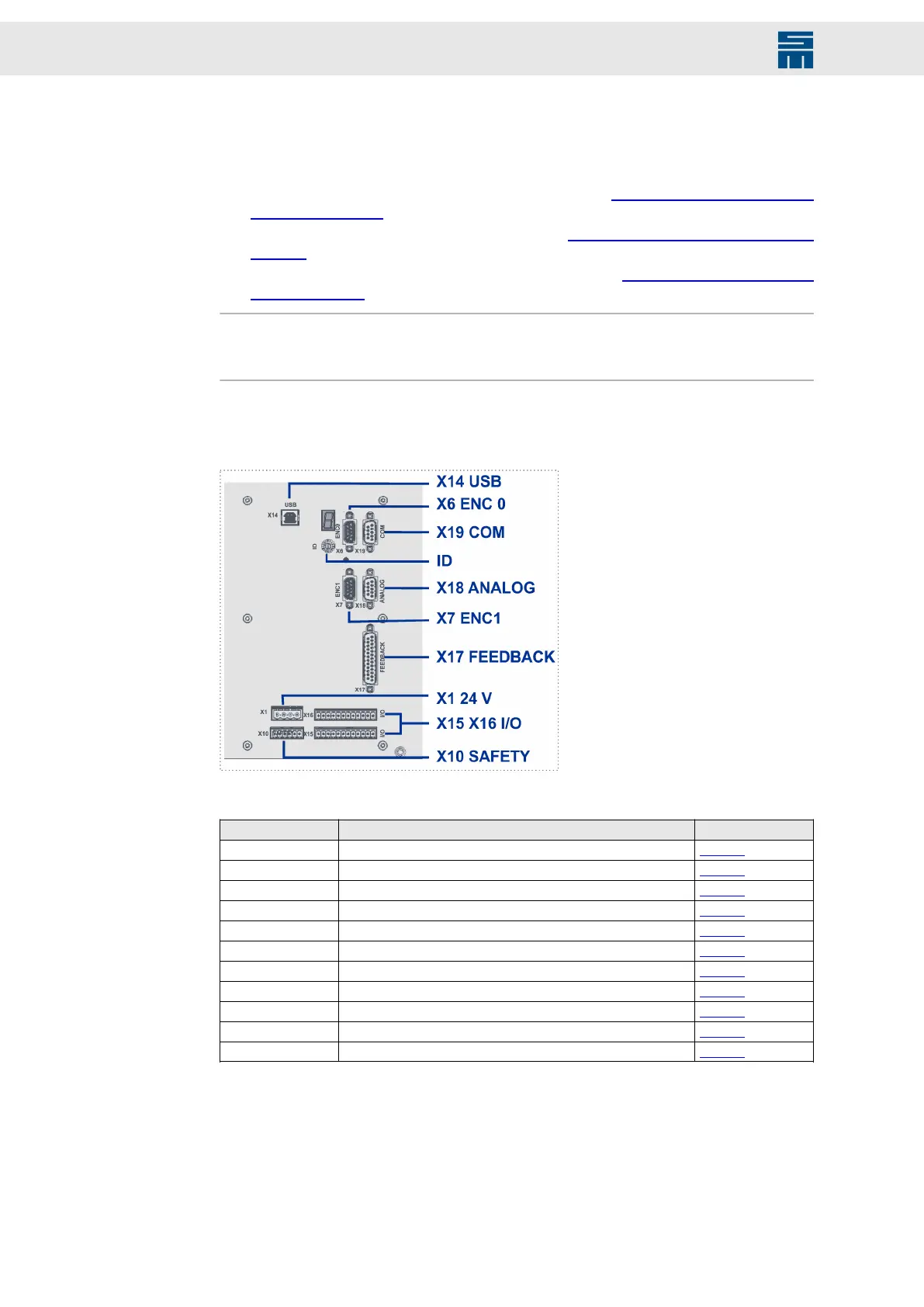
5.9.1 Front Panel Connectors
Fig. 12: Connectors at the front panel
Fig. 12: Connectors at the front panel
Connector Meaning Description
ID address selection switch page 44
X1 24 V 24-V logic voltage for power bus page 44
X6 ENC0 Encoder 0 input page 45
X7 ENC1 Input / output for Encoder 1 page 45
X10 SAFETY Safety circuit / restart lock (STO) page 46
X14 USB USB interface for parameter setting page 47
X15 I/O Digital outputs page 47
X15 I/O Digital inputs page 50
X17 Feedback Signal transmitter of the first measuring system page 52
X18 Analog Analog signals page 54
COM COM interface page 55
38 Drive System SD2M - Hardware Description 036228xxF