7.11 X19 – COM1/Operating Terminal
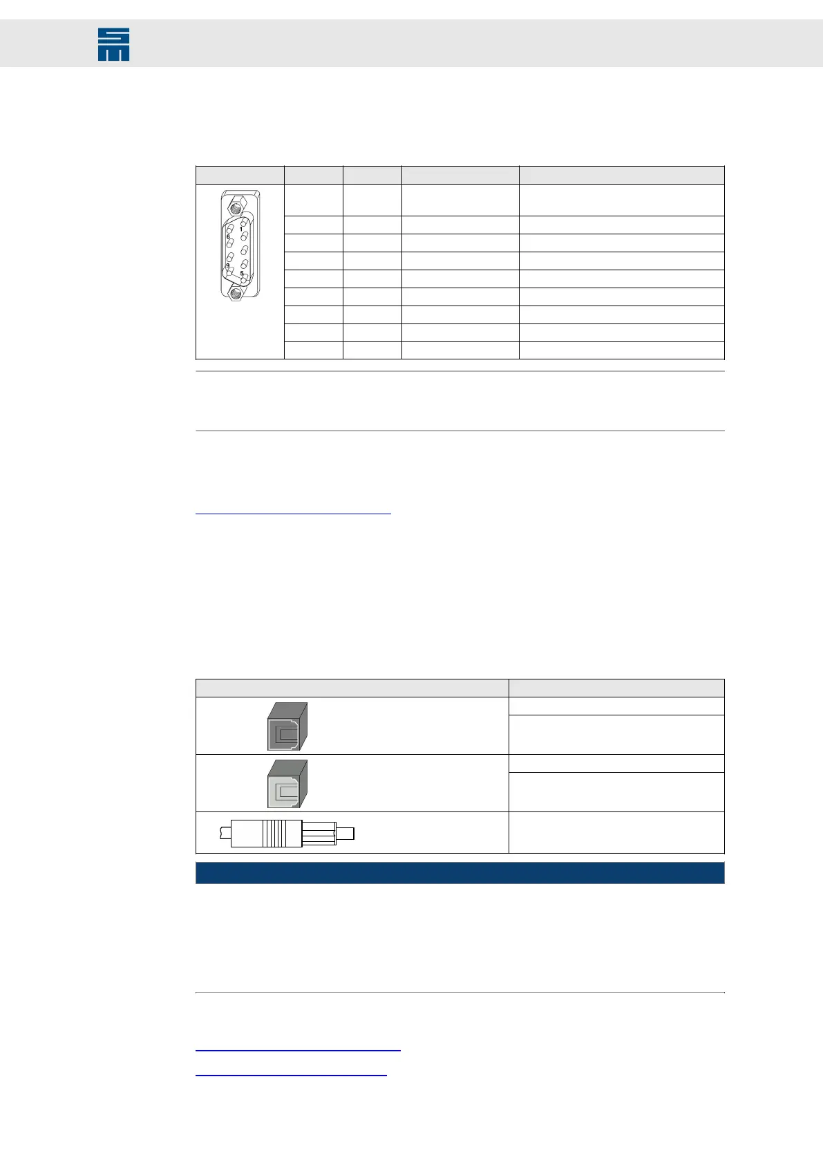
9-pole male submin D connector
X19 Pin I/O Name Meaning
1 O VCC 5.3 V (power supply for optional operat-
ing terminal, short-circuit proof)
2 I RX RS232 interface 1
3 O TX RS232 interface 1
4 I/O CAN_L CAN_L
5 I/O GND Ground
6 I RX2 RS232 Interface 2
7 O TX2 RS232 Interface 2
8 I/O CAN_H CAN_H
9 I/O GND Ground
Note
CAN bus: This is a multiport connector. Therefore the pin assignment does not comply
with the CiA standard und must be adapted accordingly.
Locking bolts flange: max. tightening torque = 0.7 Nm
Related topics
X19 – Bus Connection, page 81
7.12 X26/ X27 – SERVOLINK 4
SERVOLINK 4: optical input (X26) and optical output (X27)
The fiber optic connectors for SERVOLINK 4 are located at the bottom side of the de-
vice.
Connector SIEB & MEYER article number
12540102
Inputs (black)
12540103
12540202
Outputs (gray or white)
12540203
Cable connector
(TOSLINK F05)
32022900
NOTICE
Risk of cable damage
If you pull the optical fiber cable with its connector too fast out of the connector, the cable
may be damaged.
→ When unplugging the cable, hold the fiber optic connector and pull the cable care-
fully out of the connector.
Related topics
X26/X27 – SERVOLINK, page 83
Connection Diagram, page 111
55Drive System SD2M - Hardware Description 036228xxF
Connector Pin Assignment