Connection Examples
8 Connection Examples
The following sections provide connection examples for the individual connectors of the
device.
Wiring examples for the device connection can be found in the Appendix (p. 111).
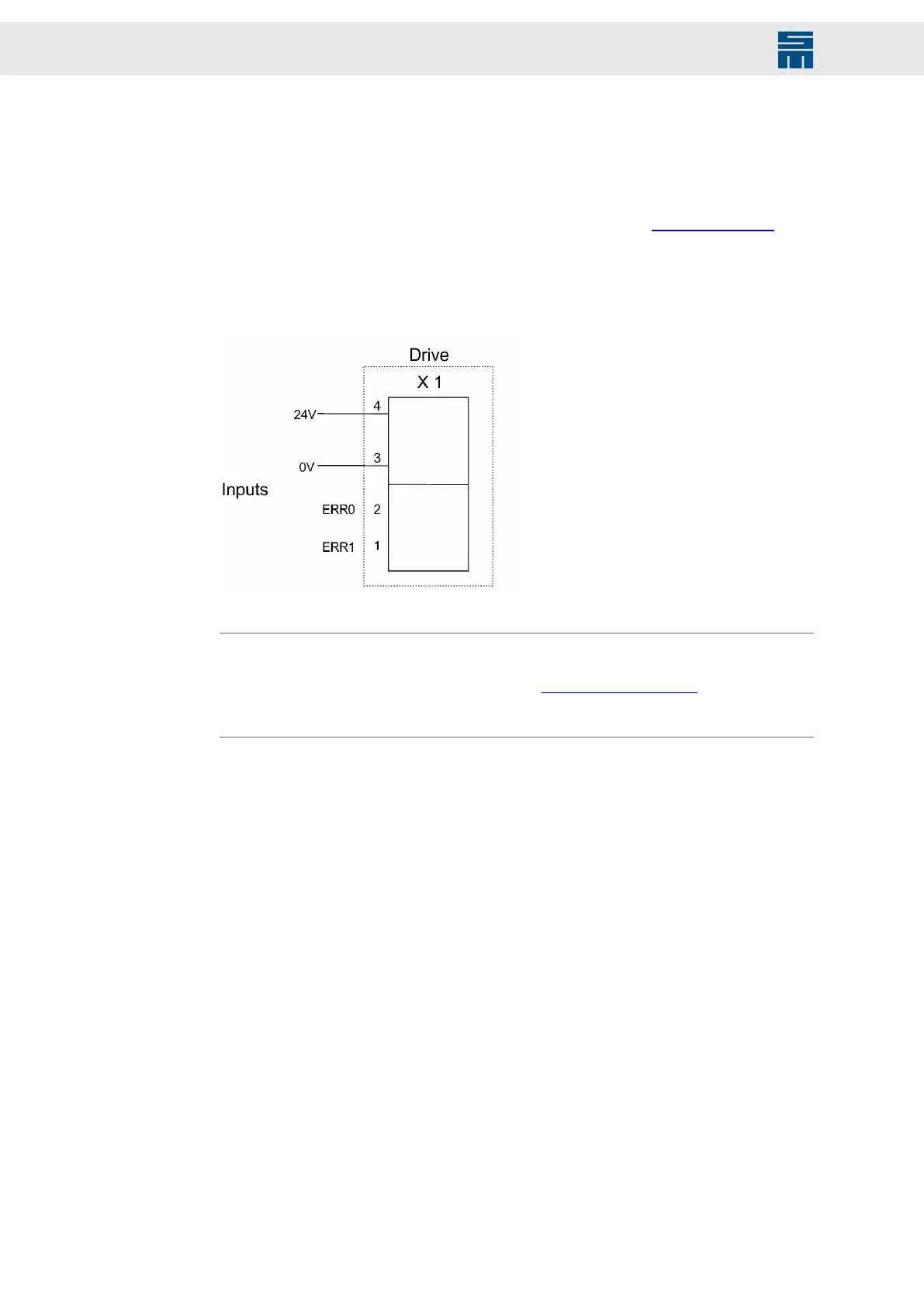
8.1 X1 – 24 V
Fig. 19: Logic voltage: 24 V ±20 %
Fig. 19: Logic voltage: 24 V ±20 %
Note
The signals ERR0 and ERR1 are inputs and provide for better error response when an
error occurs in an external power supply (see pin assignment (p. 44)). If this option is
not to be used for devices with external power supply, the inputs ERR0 and ERR1 must
be connected to 24 V. to generate the message POWER OK.
60 Drive System SD2M - Hardware Description 036228xxF