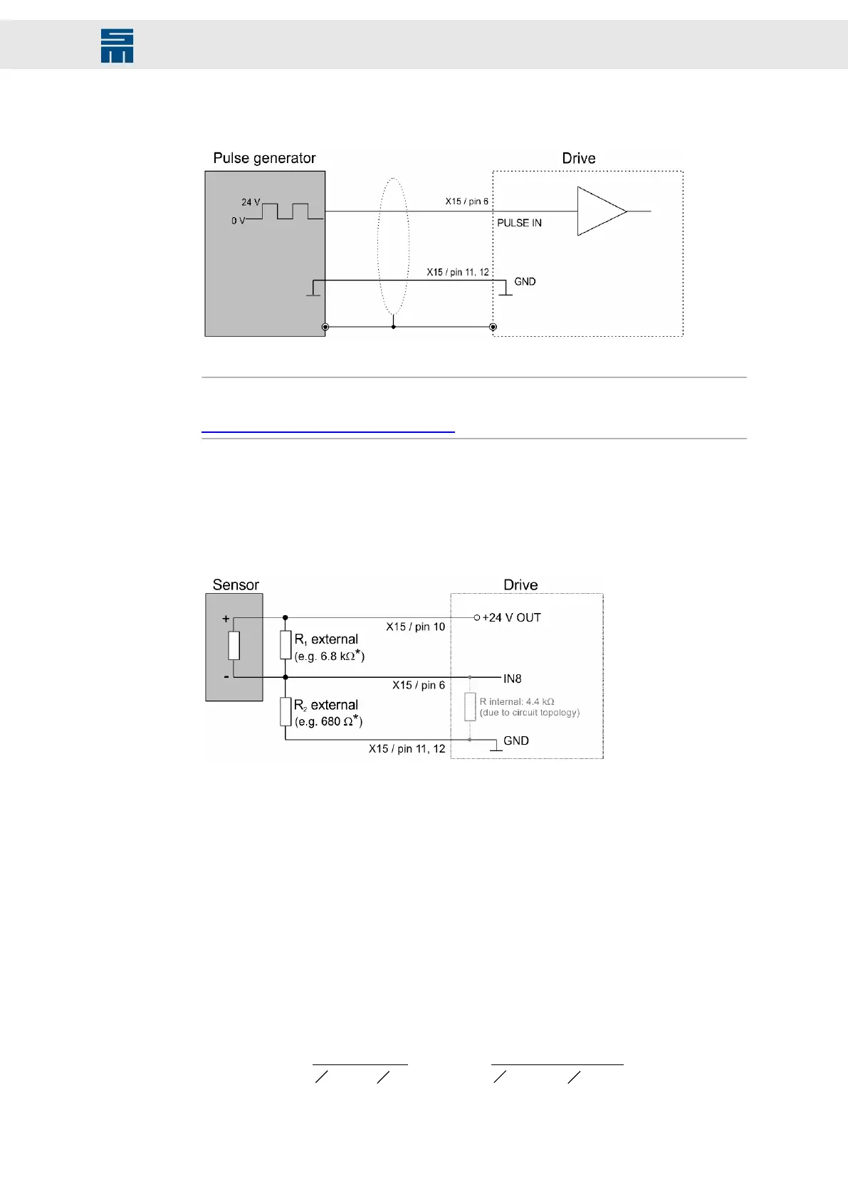
8.5.3 PULSE IN 24 V
Fig. 26: PULSE IN 24 V
Fig. 26: PULSE IN 24 V
Note
A pulse generator for 5 V is to be connected to X17 (pin 25), see connection example
chapter 8.7.11 “PULSE IN 5 V”, page 78.
8.5.4 Digital field plate / GMR
The switching thresholds of the converter input IN8 are 5.4 V for active-low signals
and 5.9 V for active-high signals. Therefore the switching thresholds of the used sen-
sor must be adapted to the input by offsetting the middle voltage.
Fig. 27: Digital field plate / GMR
Fig. 27: Digital field plate / GMR
[*] The resistors R
1
and R
2
depend on the used sensor.
Sample calculation of the resistors R
1
and R
2
The resistance is calculated by means of the spindle data.
Specifications taken from the data sheet of the spindle manufacturer:
▶ Sensor off: 4 mA (signal is not available)
▶ Sensor on: 8 mA (signal is available)
▶ Voltage U: 3 V (amplitude with 24 V supply and a resistance (R
2
) of 680 Ω)
The resistance Rinternal (4.4 kΩ) results from the circuit topology and must be included
in the calculation.
The spindle data make the following voltage levels at the input:
I
´
1
1
R
2
ext
1
Rint
+
1
1
680 W
1
4400 W
+
=
4 mA
´
=
2.36 V
Sensor off:
65Drive System SD2M - Hardware Description 036228xxF
Connection Examples