8.8.2 Analog inputs
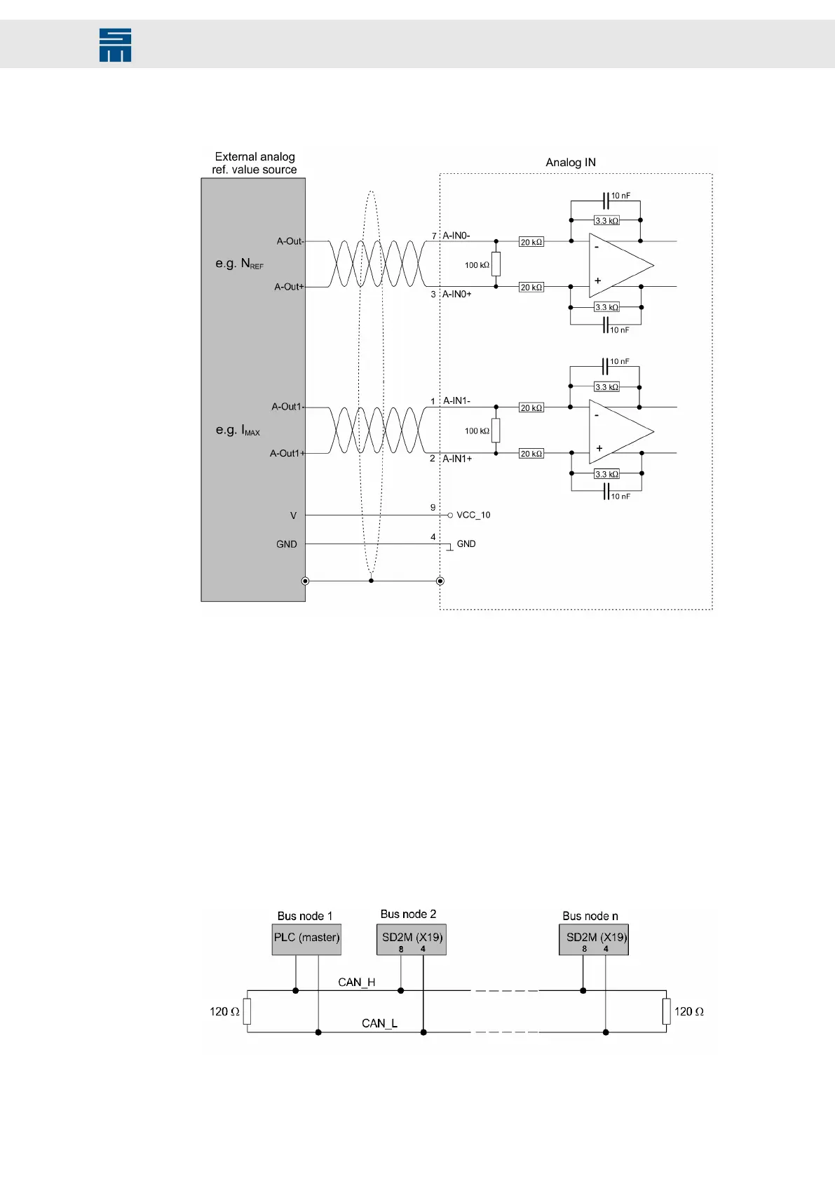
Fig. 44: Analog inputs
Fig. 44: Analog inputs
Voltage interface with input voltage range: ±10 V
Can also be connected to potentiometer (500 Ω - 5 kΩ)
8.9 X19 – Bus Connection
8.9.1 CAN Bus
The CAN interface is designed according to ISO 11898. It is a two-wire connection with
differential signals. ISO 11898 specifies a bus cable with two signal lines, CAN_H and
CAN_L. The lines have a rated impedance of 120 Ohm. The signal lines are connected
to a terminating resistor (120 Ohm) at both ends of the bus cable (see figure).
Fig. 45: CAN interface
Fig. 45: CAN interface
81Drive System SD2M - Hardware Description 036228xxF
Connection Examples