Before the shutdown of the drive, the standstill of the machine must be caused by a high-
er-ranking control and a stop function of at least category 2 must be ensured.
The restart lock interrupts the energy supply between drive and motor by cutting off the
supply of the output stage control. Thus, any rotation of the motor is made impossible.
The advantage of this circuit is that a single drive can be locked safely in an installation
with several drives, while the other drives remain in operation. Besides, a drive can be
locked without having to recharge the DC link before a restart.
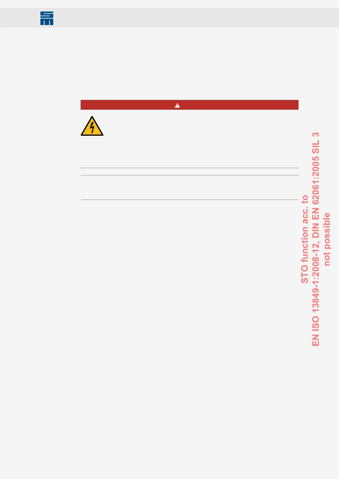
DANGER
Danger due to electric shock
The restart lock does not galvanically separate the output stages from the
motor. Thus, the restart lock does not protect against electric shock.
→ The complete machine must always be galvanically separated from
the mains by use of the main switch(DIN EN 60204-1 5.3) for any in-
terruptions of the operation, maintenance, repair or cleaning work at
the machine or system.
Note
All mounting locations for safety devices of the control system as well as components
mounted outside have to correspond to an IP Code IP54, if mounted correctly.
12.1 Functional Description of the Restart Lock
The restart lock disables the respective drive of an installation. All other drive modules
(servo amplifiers / frequency converters) remain ready for operation.
A TÜV approved safety circuit accesses relevant control units of the output stage tran-
sistors of the drive to be locked by interrupting the voltage supply of the control units.
Thus, no control pulses can be passed on to the transistors of the output stages and the
motor is at a secure standstill.
OSSD (output signal switching device)
Definition: Part of the electro-sensitive protective equipment (ESPE), which is connect-
ed with the machine control and switches into the OFF state, when the sensor unit is
triggered during the intended operation (source IEC 61496-1).
The OSSD signal is a pulsed signal, of which the phase position is shifted in relation to
the different channels. All errors can be detected by checking the pulse pattern, short-
circuit for supply, cross-circuit or defect of the device. This ensures a very high safety
level (SIL 4).
101Drive System SD2M - Hardware Description 036228xxF
Safety Circuit / Restart Lock (STO)
STO function acc. to
EN ISO 13849-1:2008-12, DIN EN 62061:2005 SIL 3
not possible