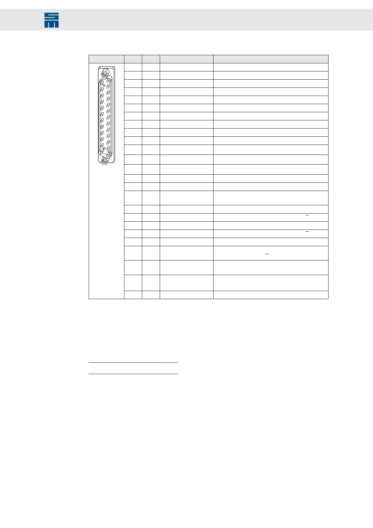
25-pole male submin D connector
X17 Pin I/O Name Meaning
1 I S2 Resolver S2
2 I S1 Resolver S1
3 I R3 Resolver R3
4 I R1 Resolver R1
5 I S4 Resolver S4
6 I S3 Resolver S3
7 I COS- SinCos/linear Hall Cosine-
8 I COS+ SinCos/linear Hall Cosine+
9 I SIN- SinCos/linear Hall Sine-
10 I SIN+ SinCos/linear Hall Sine+
11 I
HALL_C / IN4
(1)
Hall sensor 12 V track C / digital 5 V input 4
12 I
HALL_B / IN3
(1)
Hall sensor 12 V track B / digital 5 V input 3
13 I
HALL_A / IN2
(1)
Hall sensor 12 V track A / digital 5 V input 2
14 I/O GND Ground
15 I/O GND Ground
16 I TEMP Motor temperature (to be connected towards
GND)
17 I FP_IN Field plate sensor
18 I/O UB−/DATA− Encoder B− / Hall sensor 5 V differential B
19 I/O UB+/DATA+ Encoder B+ / Hall sensor 5 V differential B
20 I/O UA−/Clk− Encoder A− / Hall sensor 5 V differential A
21 I/O UA+/Clk+ Encoder A+ / Hall sensor 5 V differential A
22 I UN- Encoder ZP− / SinCos encoder zero pulse / Hall
sensor 5 V differential C
23 I UN+ Encoder ZP+ / SinCos encoder zero pulse + / Hall
sensor 5 V differential C
24 O VCC_FB Measuring system supply 5.3 V / 12 V (max.
4 W)
(2)
25 I ERR / PULSE IN Measuring system error
(1)
You can use the physical inputs HALL A to C also as the configurable, digital 5 V inputs IN2 to IN4.
(2)
Refer to the connection examples for the allowed voltage that is set by the software depending on the
selected measuring system.
Locking bolts flange: max. tightening torque = 0.7 Nm
Related topics
X17 – Motor Feedback, page 68
X16/17 – Digital Inputs, page 67
53Drive System SD2M - Hardware Description 036228xxF
Connector Pin Assignment