Connector Pin Assignment
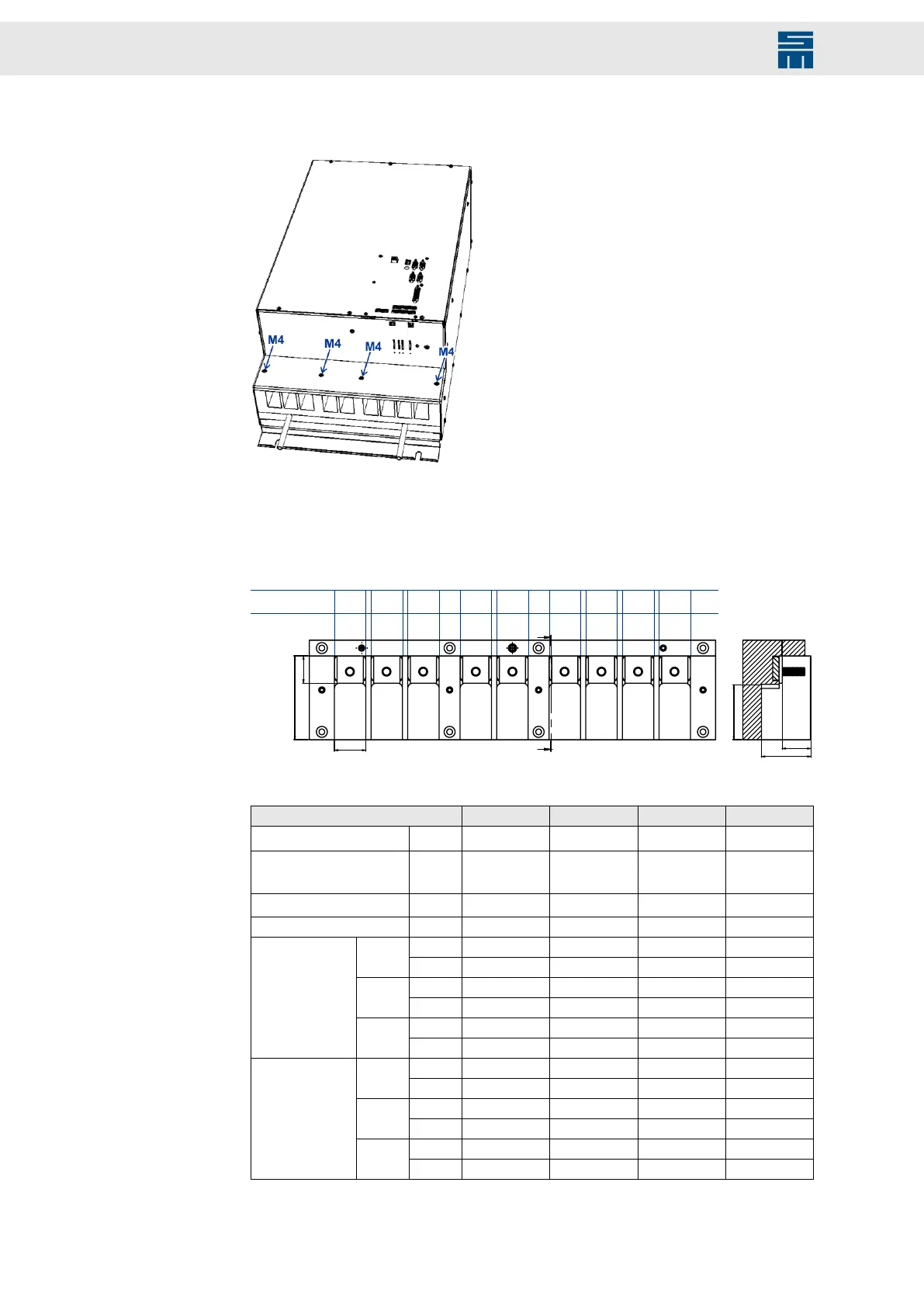
1. Remove the 4 M4 bolts (4x8, lens head screw, DIN 7985, zinc coated, Torx) of the
connector cover.
2. Connect the cables for the motor phases (U, V, W), the ballast resistor (Rext, UB
+), if existent, and the mains supply (L1, L2, L3, PE) or the external voltage supply
(UB+, UB-, PE) to the corresponding connecting bolts. Use ring cable lugs for this
purpose.
U V
W
UB- UB+
PE
U V
W
L2 L3
PE
Rext
UB+
L180AF / 81BF:
82AF / 83BF:
03622xxxx
– – –
A
A
A – A
Refer to the following table for the connection:
Device variant 03622xxxx 80AF 81BF 82AF 83BF
Max. cable cross-section
(1)
[mm²] 95 185 95 185
Min. cable cross-section
with 2 conductors
(1)
[mm²] 2 × 50 2 × 120 2 × 50 2 × 120
Bolt size M8 M10 M8 M10
Max. tightening torque [Nm] 25 49 25 49
[mm] 80 95 80 95
A
[in] 3.15 3.74 3.15 3.74
[mm] 26 37 26 37
B
[in] 1.02 1.46 1.02 1.46
[mm] 30 36 30 36
Dimensions
C
[in] 1.18 1.42 1.18 1.42
[mm] 52 58 52 58
D
[in] 2.06 2.28 2.06 2.28
[mm] 47 80 47 80
E
[in] 1.86 3.14 1.86 3.14
[mm] 28 58 28 58
Dimensions sec-
tional view (A –
A)
F
[in] 1.08 2.29 1.08 2.29
(1)
The cable cross-sections result from the measurements of the used cable lugs.
58 Drive System SD2M - Hardware Description 036228xxF