▶ Cable shields not ending in a connector inside of the switch cabinet such as motor
cables must be connected to the ground bus.
▶ Both ends of the shield of shielded cables must generally be connected to the shell.
The line cross-sections should be selected carefully so that the maximum admissible
current is not exceeded at the maximum ambient temperature (see technical data). DIN
EN 60204-1 defines the admissible values for the individual line cross-sections which
must absolutely be taken into account.
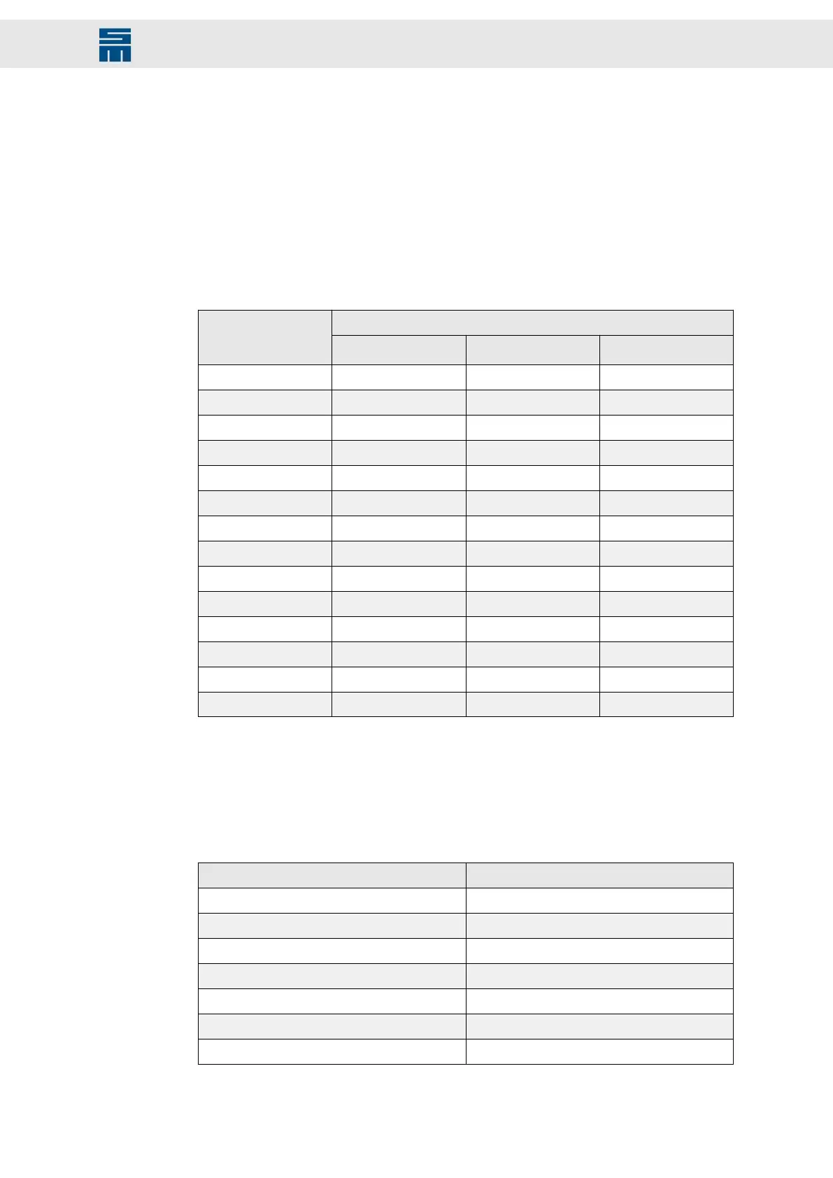
The current carrying capacity in connection with the line cross-section of copper con-
ductors isolated with PVC or cables according to DIN EN 60204-1 for different types of
wiring are indicated in the following table. All values are related to an ambient temper-
ature of +40 °C and an operating temperature at the conductor of 70 °C.
Admissible current I [A]Conductor cross-
section A [mm²]
Wiring type B2
(1)
Wiring type C
(2)
Wiring type E
(3)
0.75 8.5 9.8 10.4
1.00 10.1 11.7 12.4
1.50 13.1 15.2 16.1
2.50 17.4 21 22
4 23 28 30
6 30 36 37
10 40 50 52
16 54 66 70
25 70 84 88
35 86 104 110
50 103 125 133
70 130 160 171
95 156 194 207
120 179 225 240
Tab. 3: Current carrying capacity according to DIN EN 60204-1
Tab. 3: Current carrying capacity according to DIN EN 60204-1
(1)
cable laying in installation tubes or closed installation channels on or under the wall surface or in chan-
nels for underfloor (multicore or sheathed cables)
(2)
direct cable laying on or under the wall/ceiling or in cable trays (multicore or sheathed cables)
(3)
free cable laying with suspension ropes or on cable racks with a min. distance of 0.3 × cable diameter
to the wall (multicore or sheathed cables)
The following correction factors are provided for deviating ambient temperatures:
Ambient temperature T [°C] Correction factor
30 1.15
35 1.08
40 1.00
45 0.91
50 0.82
55 0.71
60 0.58
95Drive System SD2M - Hardware Description 036228xxF
General Information Regarding the Wiring