Connection
7.7 Connection of 3WT8 air circuit breakers
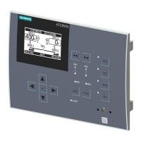
3KC ATC6500 transfer control device
138 Manual, 05/2019, L1V30538268002A-01
Note
Implementation of the power supply
More information on implementing the power supply of t
he ATC6500 via the inputs 53, 54
/ or the inputs 26, 27 can be found in chapter Connection of the power supply (Page 83).
Note
Mechanical / electrical interlocks
The two breakers of the infeed sources are not interlocked in the circuit diagram shown
above. A mechanical interlock cannot be applied either.
Note
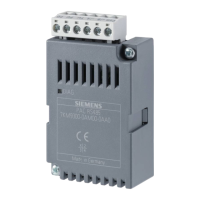
Expansion modules
For additional functions, expansion modules with inputs/outp
uts can be attached if n
Expansion modules (Page 209)).
You can find more information on the technical specifications of the circuit breaker in the
Operating Manual of the SENTRON 3WT8 air circuit breaker
(https://support.industry.siemens.com/cs/ww/en/view/33272206
).
P02.01 System configuration
- P02.22 Management of the tie breaker
Breaker pulse or breaker continuous
Breaker pulse or breaker continuous
P12.1.01 Function of the input INP1
Source 1 breaker closed (feedback 1)
P12.2.01 Function of the input INP2
Source 2 breaker closed (feedback 2)
P12.3.01 Function of the input INP3
Source 1 breaker protection (Trip 1)
P12.4.01 Function of the input INP4
Source 2 breaker protection (Trip 2)
P12.05.01 Function of the input INP5
Tie breaker TB / NPL closed (feedback message)
P12.06.01 Function of the input INP6
Tie breaker TB / NPL protection (Trip)
P13.1.01 Function of the output OUT1
P13.2.01 Function of the output OUT2
58 (OUT3) P13.3.01 Function of the output OUT3 Open Source 2 breaker
P13.4.01 Function of the output OUT4
P13.12.01 Function of the output OUT12
Open tie breaker TB / NPL
P13.13.01 Function of the output OUT13
Close tie breaker TB / NPL
 Loading...
