Dimensions for the securing holes
The following table contains the dimensions for the holes for securing mounting rails.
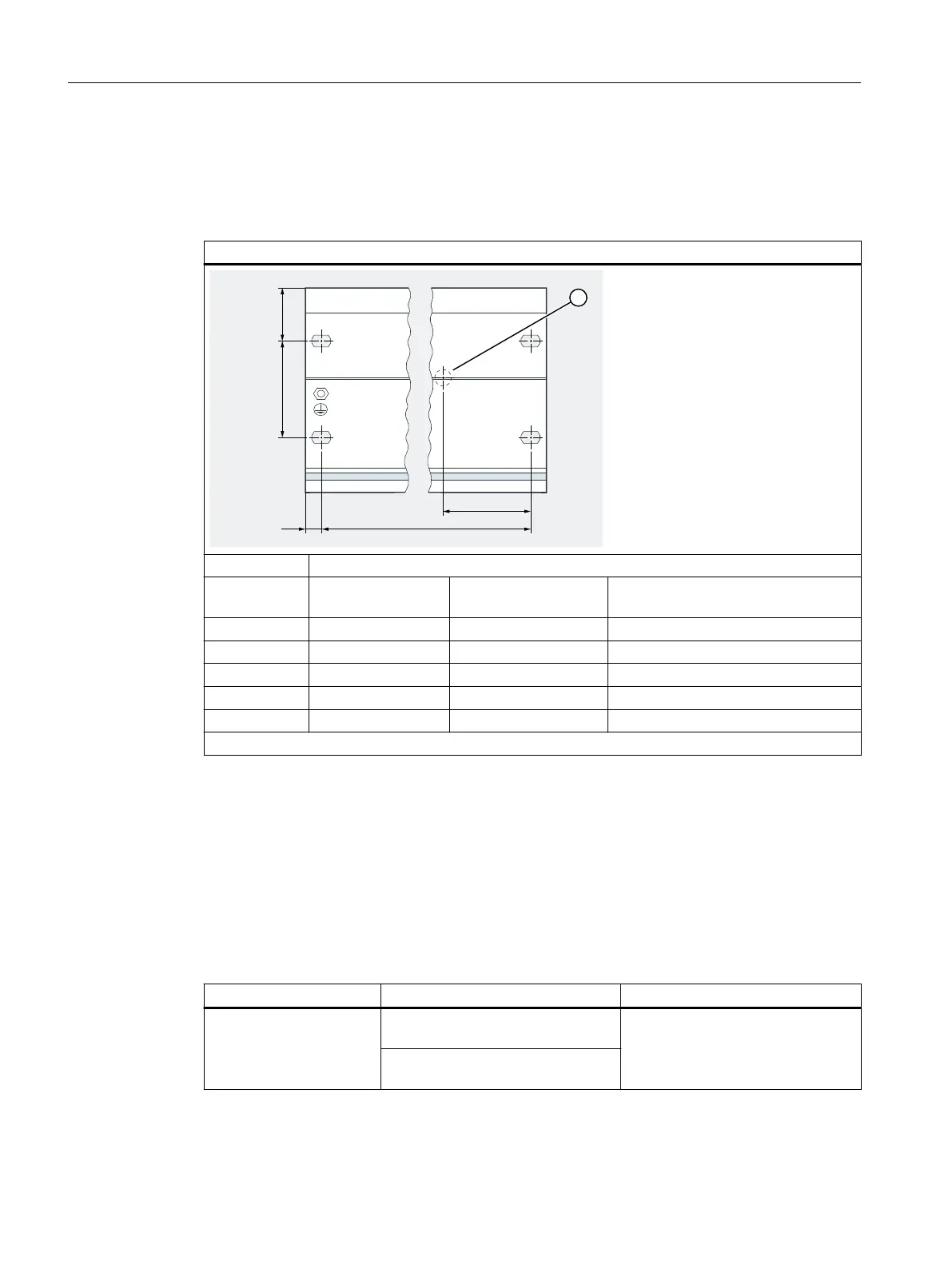
Table 5-2 Diagram for securing mounting rails
"Standard" Mounting Rail
① Mark for additional bore hole for applications with increased vibration and shock stress.
Length of the
mounting rail
Distance a Distance b Maximum number of terminal mod‐
ules
1
within distance b
482.6 mm 8.3 mm 466 mm 6
530 mm 15 mm 500 mm 7
585 mm 8.5 mm 568 mm 8
830 mm 15 mm 800 mm 12
885 mm 8.5 mm 868 mm 13
1
Width of the terminal modules: 60 mm
Required tools
Wrench or screwdriver suitable for selected securing screws.
Required accessories
To secure the mounting rail, you can use the following types of screws:
Table 5-3 Securing screws
For You can use... Explanation
Outer securing screws Cylinder head screw M6 according to
ISO 1207/ISO 1580 (DIN 84/DIN 85)
Select the screw length to suit the
situation.
You will also need washers 6.4 ac‐
cording to ISO 7092 (DIN 433).
Cylinder head screw M6 according to
ISO 4017 (DIN 4017)
Installing
5.2 Installing the mounting rail
ET 200iSP
108 Operating Instructions, 11/2022, A5E00247483-AK