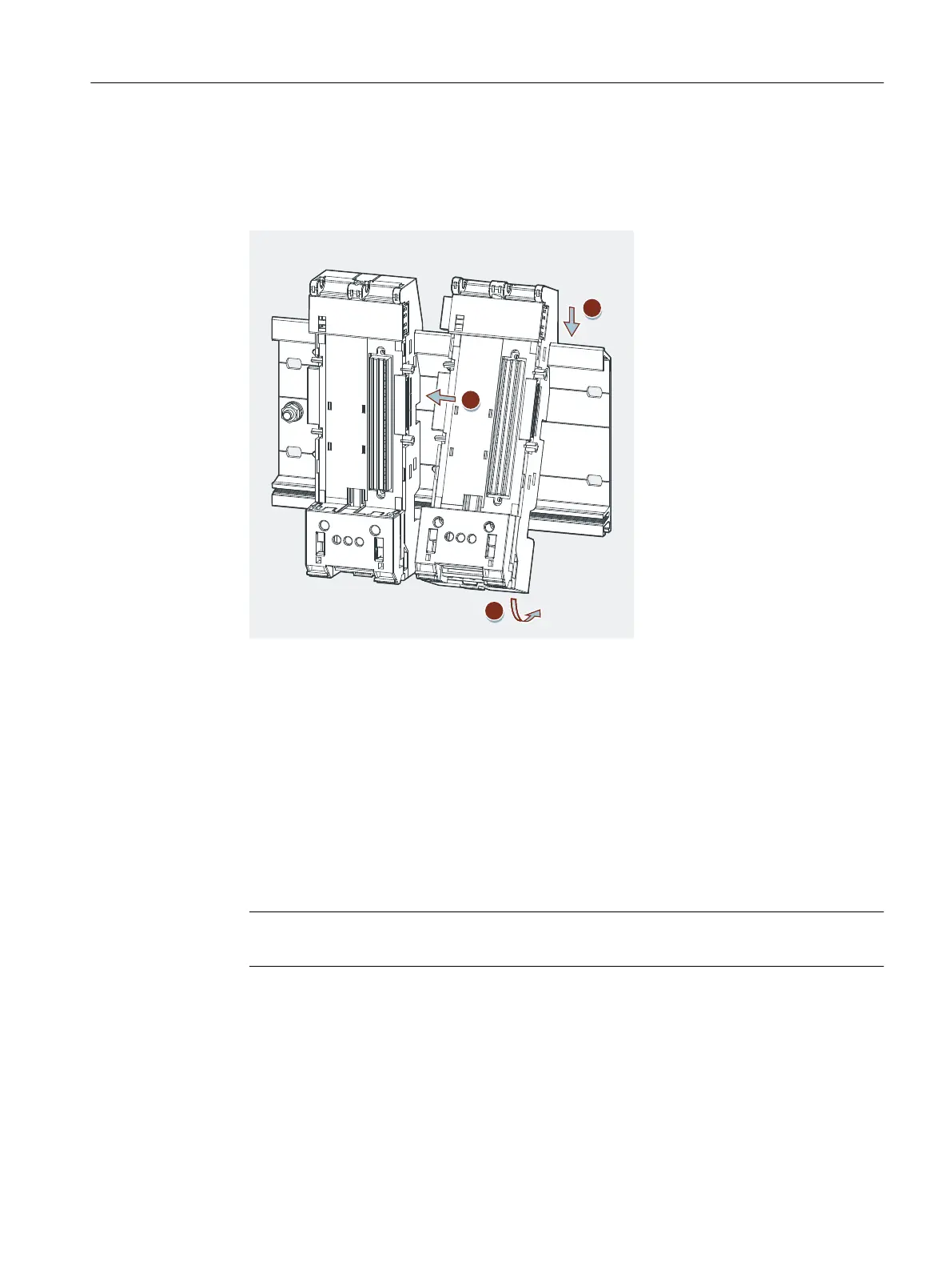
3. Move the TM‑PS‑B to the left until it audibly latches onto the previous terminal module
TM‑PS‑A.
4. Bolt the terminal module to the mounting rail. See Installing terminal module TM‑PS‑A Step
3.
5.14"5.14"6$
5.14#5.14#6$
Figure 5-7 Installing terminal module TM‑PS‑B
Removing terminal module TM‑PS‑A or TM‑PS‑B
Requirements: The terminal module is wired and to the right of it there are other terminal
modules.
1. Switch o the supply voltage of the terminal module TM‑PS‑A and, if present, at TM‑PS‑B.
2. Loosen the wiring on the terminal module TM‑PS‑A with the screwdriver.
3. Release the two fastening screws of the terminal module.
4. Use the screwdriver to lever the slide on the terminal module TM‑PS‑A downward as far as it
will go and move the terminal module to the left.
Note
The slider is located below the terminal module (see gure above).
5. While pulling on the slider, swivel the terminal module o the mounting rail.
6. If available, repeat steps 2 to 5 for the terminal module TM‑PS‑B.
Installing
5.3 Installing the terminal module for power supply PS
ET 200iSP
Operating Instructions, 11/2022, A5E00247483-AK 111