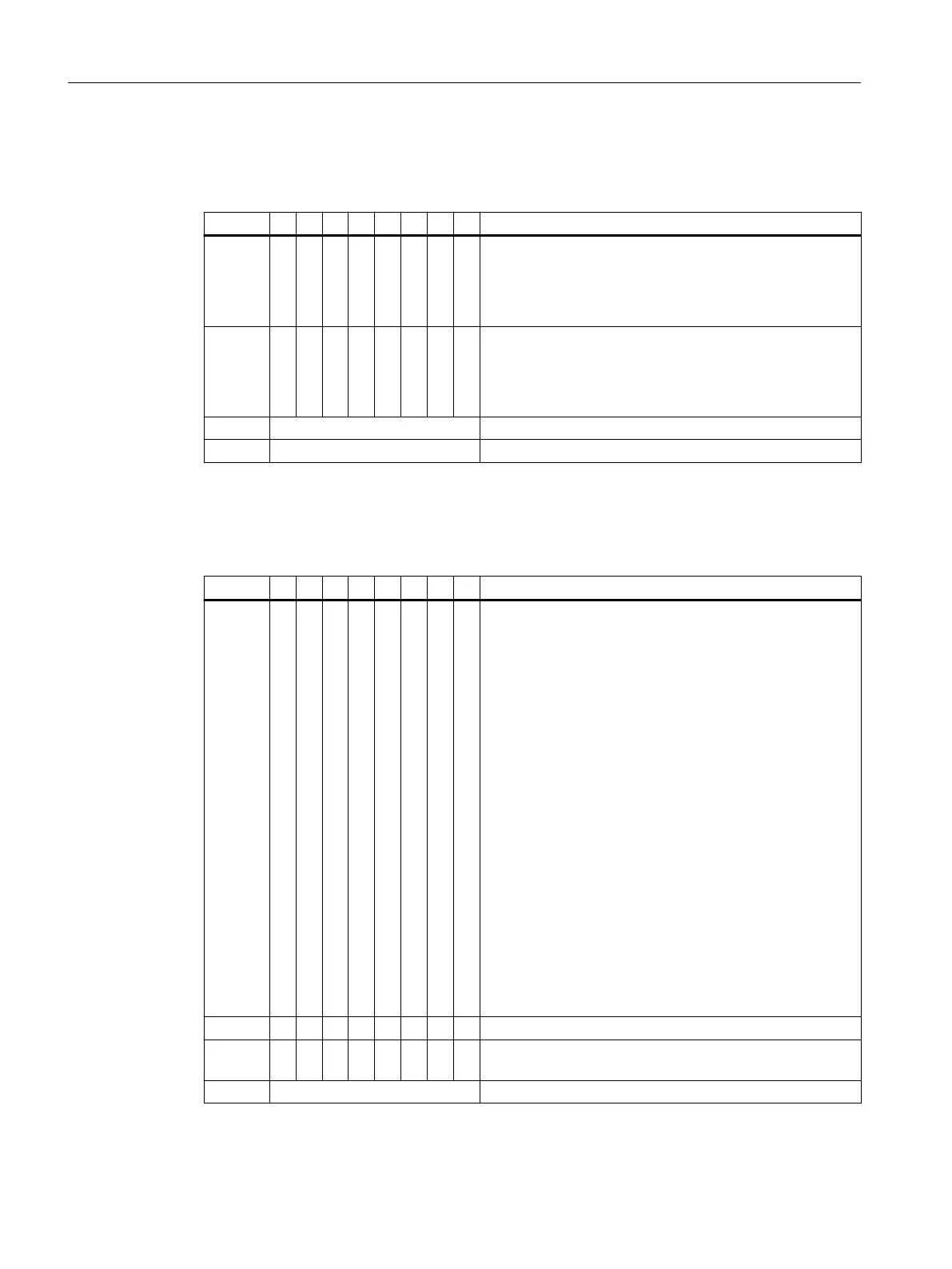
Hardware interrupt for analog input modules
Table 7-45 Conguration from byte x+4 for hardware interrupt (analog input)
Byte 7 6 5 4 3 2 1 0 Description
Byte x+4 Bit 0: 1: Violation of the high limit channel 0
Bit 1: 1: Violation of the high limit channel 1
Bit 2: 1: Violation of the high limit channel 2
Bit 3: 1: Violation of the high limit channel 3
Byte x+5 Bit 0: 1: Violation of the low limit channel 0
Bit 1: 1: Violation of the low limit channel 1
Bit 2: 1: Violation of the low limit channel 2
Bit 3: 1: Violation of the low limit channel 3
Byte x+6 Always 00
H
Byte x+7 Always 00
H
Hardware interrupt time stamping at slot 2 (IM 152-1DP)
Table 7-46 Conguration from byte x+4 for hardware interrupt (time stamping)
Byte 7 6 5 4 3 2 1 0 Description
Byte x+4 Time stamping status
Bit 0: 1: Message buer is ready for retrieval on IM 152-1DP
Bit 1: 1: Overow of the message buer "external": Permis‐
sible message buers are lled.
Bit 2: 1: Overow of the message buer "internal": There is
a risk of message loss.
Bit 3: Redundancy: Active IM 152-1DP
0: Right IM of the TM-IM/IM is the active one
1: Left IM of the TM-IM/IM is the active one
Bit 4: Redundancy: Redundancy mode active/not active
0: No redundant operation
1: Redundant operation
Bit 5: Resetting the time stamping
0: no resetting takes place
1: Reset just completed
Bit 6: Not applicable
Bit 7: State of synchronization via time frame
0: No synchronization available
1: Synchronization available
Byte x+5 Data record number, if a data record is to be retrieved
Byte x+6 Number of message blocks contained in the data record 1 to
20
Byte x+7 Reserved
Commissioning and Diagnostics
7.13 Diagnostics with STEP 7 with PROFIBUS
ET 200iSP
218 Operating Instructions, 11/2022, A5E00247483-AK