Pull/plug interrupt
The byte x+4 to x+8 contains the identication of the module that was removed or inserted. The
identier for the individual modules can be found in the GSD le.
You can tell whether the modules have been pulled out or plugged in by the interrupt type in byte
x+1 (see table Conguration of the interrupt status of the interrupt part).
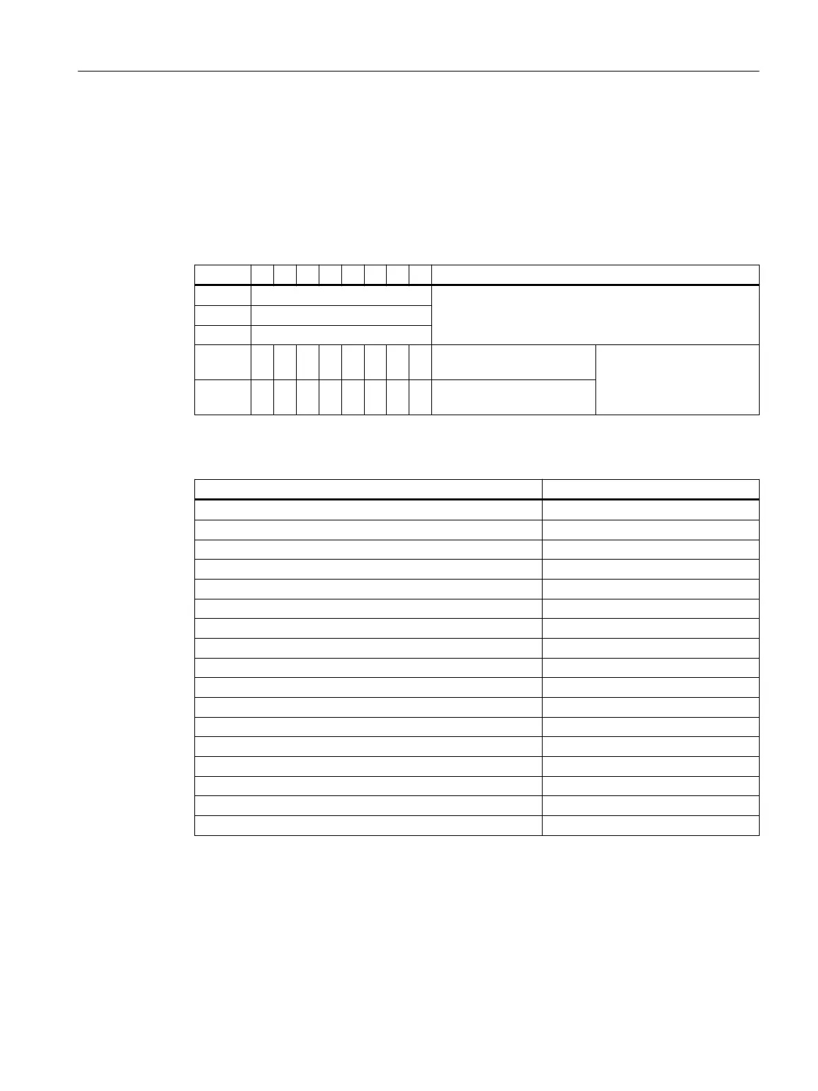
Table 7-47 Conguration from byte x+4 for pull/plug interrupt
Byte 7 6 5 4 3 2 1 0 Description
Byte x+4 Not applicable
Byte x+5
Byte x+6
Byte x+7 Type recognition of the mod‐
ule; high byte
SKF identier (STEP 7), see
table below
Byte x+8 Type recognition of the mod‐
ule; low byte
Table 7-48 SKF identiers (STEP 7)
Modules SKF identier
8 DI NAMUR 79 CA
H
4 DO DC23.1V/20mA shut down "H" 79 D1
H
4 DO DC17.4V/27mA shut down "H" 79 D2
H
4 DO DC17.4V/40mA shut down "H" 79 D3
H
4 DO DC23.1V/20mA shut down "L" 79 D5
H
4 DO DC17.4V/27mA shut down "L" 79 D6
H
4 DO DC17.4V/40mA shut down "L" 79 D7
H
2 DO Relay UC60V/2A 79 D4
H
4 AI I 2WIRE HART 79 EB
H
4 AI I 4WIRE HART 79 EC
H
4 AI RTD 79 EF
H
4 AI TC 79 EE
H
4 AO I HART 79 F2
H
Reserve module 8F C0
H
WATCHDOG module 79 DD
H
Pulled module DE C0
H
Reserve identier (CiR) B6 40
H
Update interrupt
The update interrupt is reported when the following conditions are met:
• The parameter assignment has been carried out without errors.
• The parameter assignment of the ET 200iSP is dierent from the parameters and
identication and maintenance data stored retentively in the modules.
Commissioning and Diagnostics
7.13 Diagnostics with STEP 7 with PROFIBUS
ET 200iSP
Operating Instructions, 11/2022, A5E00247483-AK 219