Pin assignment of actuators
Table 13-8 Pin assignment of actuators
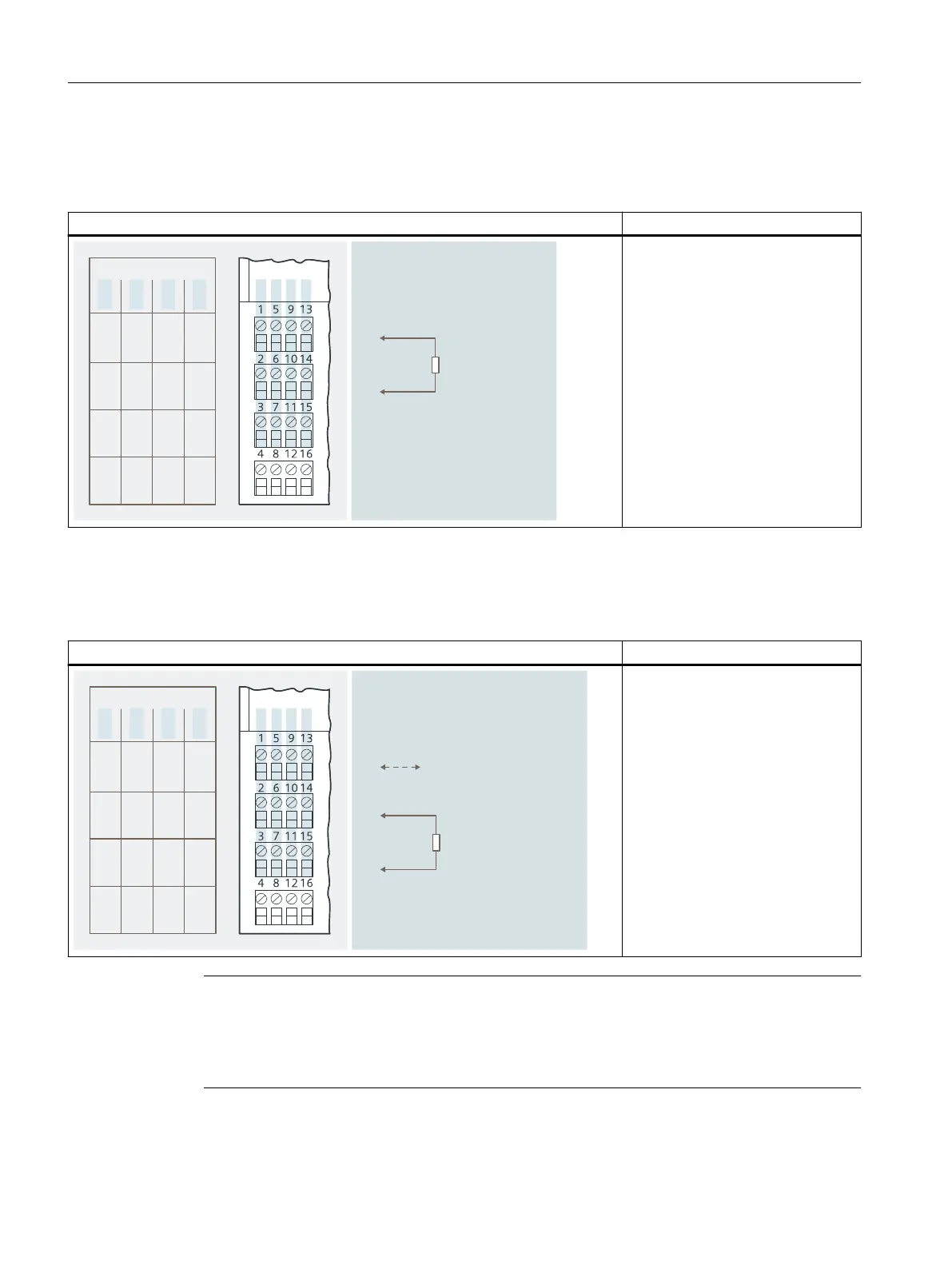
Pin assignment and view Remarks
$POOFDUJPOFYBNQMF
"DUVBUPSPO
DIBOOFM
$IBOOFM
%0ݲ
%0ݳ
%0ݴ
%0ݵ
%0ݲ%0ݴ
....
4*
4*
4*
.
4*
.
Actuator terminals:
Channel 0: Terminals 1 and 2
Channel 1: Terminals 5 and 6
Channel 2: Terminals 9 and 10
Channel 3: Terminals 13 and 14
DO: Digital outputs
M: Ground
Pin assignment for enhanced performance (only for 4 DO DC17.4V/27mA, 4 DO DC17.4V/40mA)
Table 13-9 Pin assignment for enhanced performance
Pin assignment and view Remarks
$POOFDUJPOFYBNQMFGPSQPXFS
JODSFBTFCZQBSBMMFMDPOOFDUJPOPG
DIBOOFMBOEDIBOOFM
+VNQFSGPSJODSFBTFE
QFSGPSNBODF
FHBDUVBUPSPO
$IBOOFM
$IBOOFM
%0ݲ
%0ݳ
%0ݴ
%0ݵ
%0ݲ%0ݴ
....
4*
4*
4*
.
4*
.
Increased power:
Parallel connection of channel 0 and
channel 1: Jumper from 1 to 5; ac‐
tuator at 2 and 3
Parallel connection of channel 2 and
channel 3 Jumper from 9 to 13; ac‐
tuator at 10 and 11
DO: Digital outputs
M: Ground
Note
If the actuator shutdown signal is connected in parallel via terminals 4/8 and 12/16, note that
this signals is interrupted when a 4 DO module is pulled. If "hot swapping" is intended when the
actuator disconnection is activated, the individual modules must be connected directly to the
signal source.
Digital electronic modules
13.2 Digital electronics module 4 DO
ET 200iSP
306 Operating Instructions, 11/2022, A5E00247483-AK