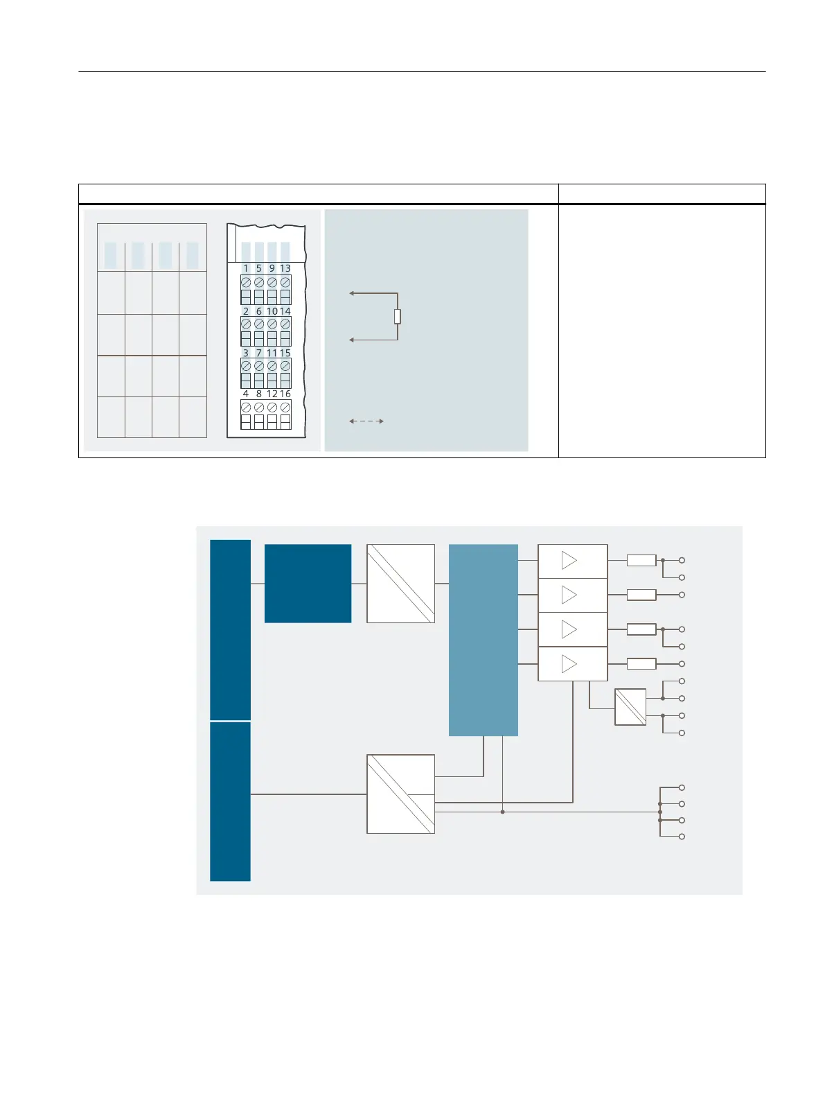
Pin assignment for actuator disconnection
Table 13-10 Pin assignment for actuator disconnection
Pin assignment and view Remarks
$POOFDUJPOFYBNQMFGPSBDUVBUPS
EJTDPOOFDUJPO
*OQVUGPSBDUVBUPS
EJTDPOOFDUJPO
FHBDUVBUPSPO
$IBOOFM
$IBOOFM
%0ݲ
%0ݳ
%0ݴ
%0ݵ
%0ݲ%0ݴ
....
4*
4*
4*
.
4*
.
Actuator disconnection of all out‐
puts channel 0 to channel 3:
Terminal 4/8: High active (intrinsical‐
ly safe) or low active signal (see g‐
ure, "Actuator disconnection via in‐
trinsically safe shutdown signal for
shut down "H" output modules")
Terminal 12/16: Ground
DO: Digital outputs
M: Chassis ground
SI
+
: Signal input for actuator discon‐
nection
SI
M
: Ground
Block diagram
#BDLQMBOFCVT
DPOOFDUJPO
1PXFSCVT#BDLQMBOFCVT
u$
.
%0ݲ
%0ݳ
%0ݴ
%0ݵ
4*
4*
4*
.
4*
.
.
.
.
Figure 13-2 Block diagram of 4 DO
Digital electronic modules
13.2 Digital electronics module 4 DO
ET 200iSP
Operating Instructions, 11/2022, A5E00247483-AK 307