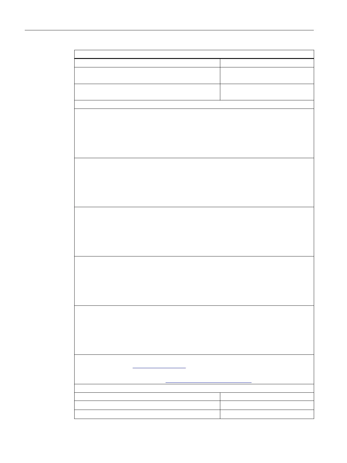
Technical specications
Monitoring for
• Short-circuit
R < 80 Ω (one output)
R < 40 Ω (outputs connected in parallel)
• Wire break
R
1
> 10 kΩ
I < 100 µA
Safety data
Maximum values for intrinsically safe switching signal SO:
U
i
= 28 V
I
i
= not relevant
P
i
= 1.2 W
C
i
= 3 nF
L
i
= 0 mH
Modules 4 DO 6ES7132-7RD01-0AB0 and 6ES7132-7GD00-0AB0:
U
o
= 25.6 V
I
o
= 96 mA
P
o
= 0.61 W
C
o
= 98 nF
L
o
= 3 mH
Modules 4 DO 6ES7132-7GD30-0AB0:
U
o
= 27.9 V
I
o
= 110 mA
P
o
= 0.76 W
C
o
= 81 nF
L
o
= 3 mH
Modules 4 DO 6ES7132-7RD22-0AB0 and 6ES7132-7GD21-0AB0:
U
o
= 19.4 V
I
o
= 118 mA
P
o
= 0.57 W
C
o
= 0.24 μF
L
o
= 2.5 mH
Modules 4 DO 6ES7132-7RD11-0AB0 and 6ES7132-7GD10-0AB0:
U
o
= 19.4 V
I
o
= 132 mA
P
o
= 0.64 W
C
o
= 0.23 μF
L
o
= 1.9 mH
For additional C
o
/ L
o
combinations, see certicate IECEx KEM 05.0011
https://www.iecex.com (https://www.iecex.com)
KEMA 04 ATEX1249 INMETRO UL-BR 12.0073
https://support.industry.siemens.com (https://support.industry.siemens.com)
Actuator selection data
No load voltage U
AO
• 4 DO DC25.5V/22mA shut down "L"
min. 25.5 V
• 4 DO DC23.1V/20mA shut down "H"/"L"
min. 23.1 V
Digital electronic modules
13.2 Digital electronics module 4 DO
ET 200iSP
322 Operating Instructions, 11/2022, A5E00247483-AK