Pin assignment
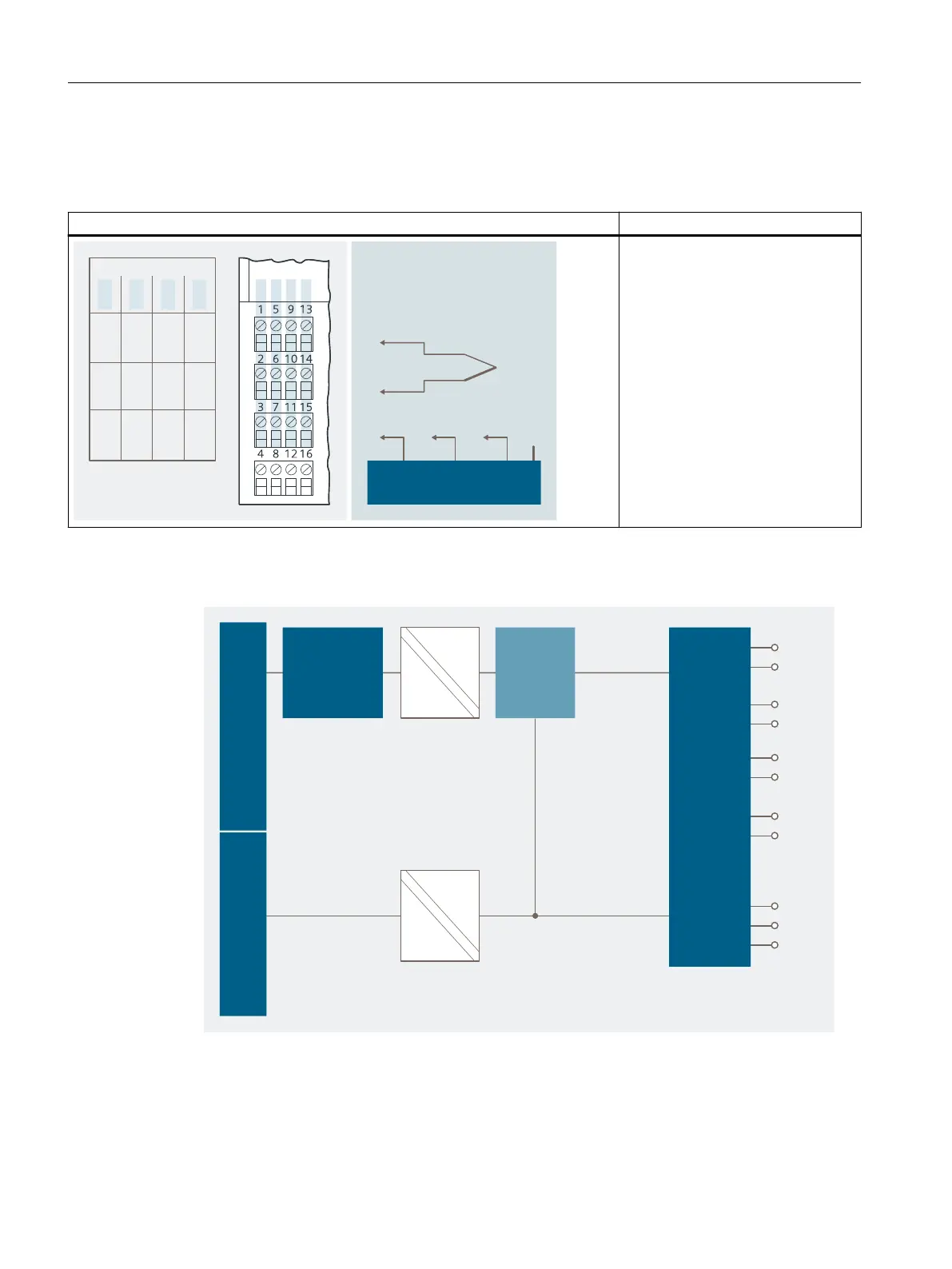
Table 14-7 Pin assignment of the 4 AI TC
Pin assignment and view Remarks
$POOFDUJPOFYBNQMFGPS
DIBOOFM
$IBOOFM
5$TFOTPSNPEVMF
.
.
.
.
....
5$
5$
5$
5$
Thermocouple 1
Channel 0: Terminals 1 and 2
Thermocouple 2
Channel 1: Terminals 5 and 6
Thermocouple 3
Channel 2: Terminals 9 and 10
Thermocouple 4
Channel 3: Terminals 13 and 14
TC sensor module
Terminals 3, 7, 11, 15
M+: Measuring cable (positive)
M-: Measuring cable (negative)
Block diagram
#BDLQMBOFCVT
DPOOFDUJPO
1PXFSCVT#BDLQMBOFCVT
0QUP
NVMUJQMFYFS
$POWFSUFS
*OQVUT
5$TFOTPS
NPEVMF
u$
Figure 14-4 Block diagram of the 4 AI TC
Analog electronic modules
14.5 Analog electronics module 4 AI TC
ET 200iSP
364 Operating Instructions, 11/2022, A5E00247483-AK