4. Connect a separate power supply to each TM.
5. Finally, t the TMs with Power Supply PS 1 and PS 2.
5.14"
5.14"6$
5.14#
5.14#6$
1414
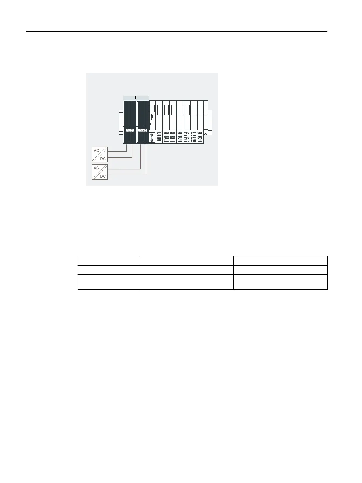
Figure 4-7 Redundancy of the power supply (example with IM 152-1DP)
Parameter assignment
Only those parameters that are relevant for the redundancy of the power supply are explained
below. These are part of the interface module parameters.
Table 4-8 Parameters for redundancy of the Power Supply PS
Parameters Setting Description
Self-diagnosis Enabled ---
Redundant Power Sup‐
ply diagnostics
Redundant Power Supply Diagnostics in the event of failure of
Power Supply PS 1 or PS 2
See also
Power supply PS 120/230 VAC (Page 272)
Power supply PS 24 VDC (Page 269)
Congurations (principle)
4.12 Redundancy of the Power Supply
ET 200iSP
84 Operating Instructions, 11/2022, A5E00247483-AK