Parameters
4.7 Standard functions
SIMOCODE pro - Parameterize
206 Operating Manual, 04/2017, A5E40507630002A/RS-AA/001
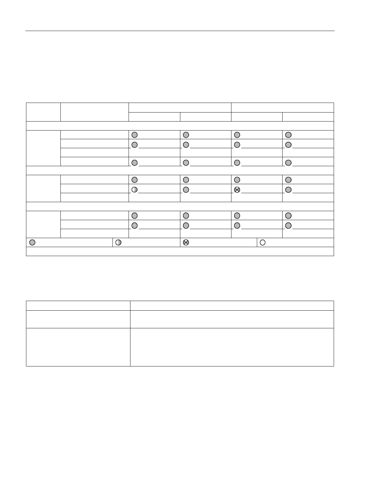
The following table shows the test phases performed when the "TEST / RESET" button is
pressed for the required length of time:
Table 4- 68 States of the status LEDs / contactor controls during testing
1)
Hardware test / lamp test
< 2s
Results of the hardware test / lamp test
2 to 5s
> 5s
1) "Fault" only displayed after 2 s
Table 4- 69 Test settings
Input
Activation of the "Test" function block by any signal (any sockets, e.g. device
inputs, communication bus control bits, etc.).
Test / Reset buttons blocked The blue TEST/RESET buttons on the basic unit and the operator panel are
usually intended for acknowledging faults and for performing a device test.
The buttons can be disabled with "TEST/RESET keys disabled". These can then
be used for other purposes. On the operator panel with display, blocking is
carried out via the corresponding menu function. (Default: not disabled)