Parameters
4.5 Inputs
SIMOCODE pro - Parameterize
196 Operating Manual, 04/2017, A5E40507630002A/RS-AA/001
Cyclic Receive
Description
With the "Cyclic Receive" function blocks, you can specify which cyclic data from the
automation system will be further processed in SIMOCODE pro. These will normally be
PLC / PCS binary control commands. Connection with the "Control stations" function block in
SIMOCODE pro will allow the motor to be controlled via
PROFIBUS DP / PROFINET / EtherNet/IP. Direct connection of the analog value with the
"AM Output" function block will result in, for example, the cyclic output of the value sent via
the communication bus at the output of the analog module.
The "Cyclic receive" function blocks consist of:
● 16 bits (byte 0 and byte 1 for binary information)
● One word (= two bytes, byte 2 to 3 for an analog value, freely programmable) for basic
type 1.
Overall there are four "Cyclic Receive" function blocks (0, 1, 2/3, 4/5).
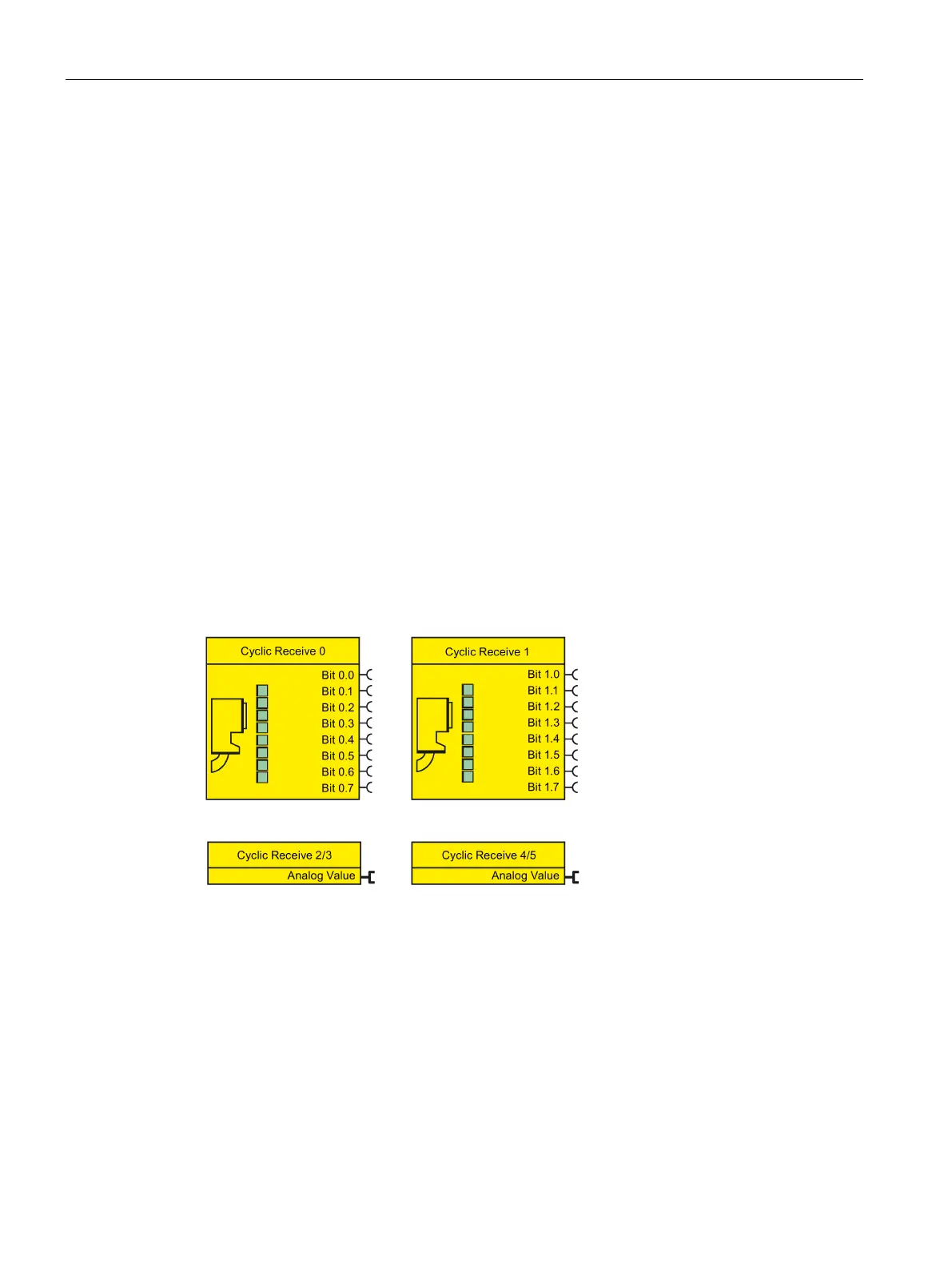
The following schematic shows the "Cyclic receive" function blocks:
Figure 4-69 Function schematic of cyclic receive data
The cyclic data is exchanged between master and slave in every communication cycle. The
master sends the cyclic receive data (Cyclic Receive) to SIMOCODE pro each time.
SIMOCODE pro responds by sending the cyclic send data (Cyclic Send) to the master.