Parameters
4.8 Logic modules
SIMOCODE pro - Parameterize
Operating Manual, 04/2017, A5E40507630002A/RS-AA/001
241
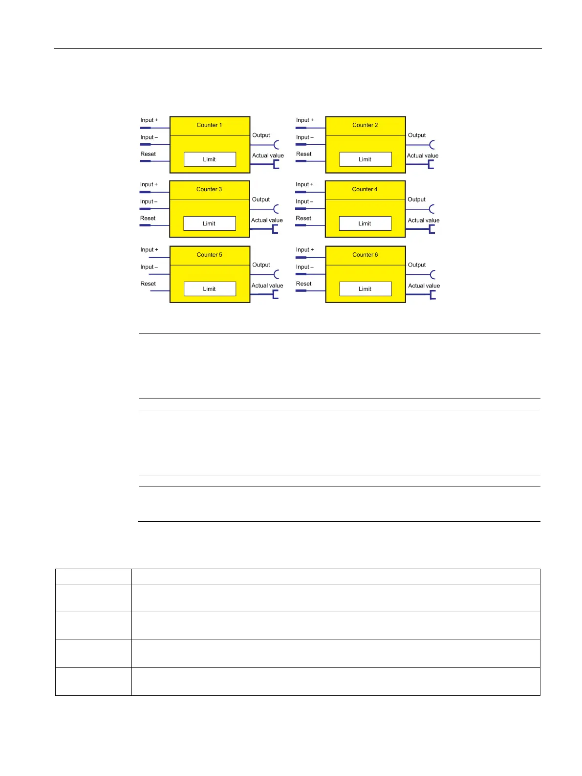
The following schematic shows the "Counters" logic modules:
Figure 4-95 "Counter" logic modules
Note
The time between the events to be counted depends on
The input delay
The device cycle time.
Note
The actual value remains
the same
During parameterization or failure of the supply voltage
If there are simultaneous input signals at input + and input -.
Note
The output is always 0 if a reset is pending.
Table 4- 88 Counter settings
Input + Increments actual value by 1
Activation by any signal (any sockets, e.g. device inputs, control bits from the communication bus, etc.)
Input - Decrements the actual value by 1.
Activation by any signal (any sockets, e.g. device inputs, control bits from the communication bus, etc.)
Reset Reset the actual value to 0 (count value and output).
Activation by any signal (any sockets, e.g. device inputs, control bits from the communication bus, etc.)
Limit Value that can be reached when counting and at which the counter issues an output signal.
Range: 0 to 65535 (default: 0)