Commissioning Manual
152 01/2017
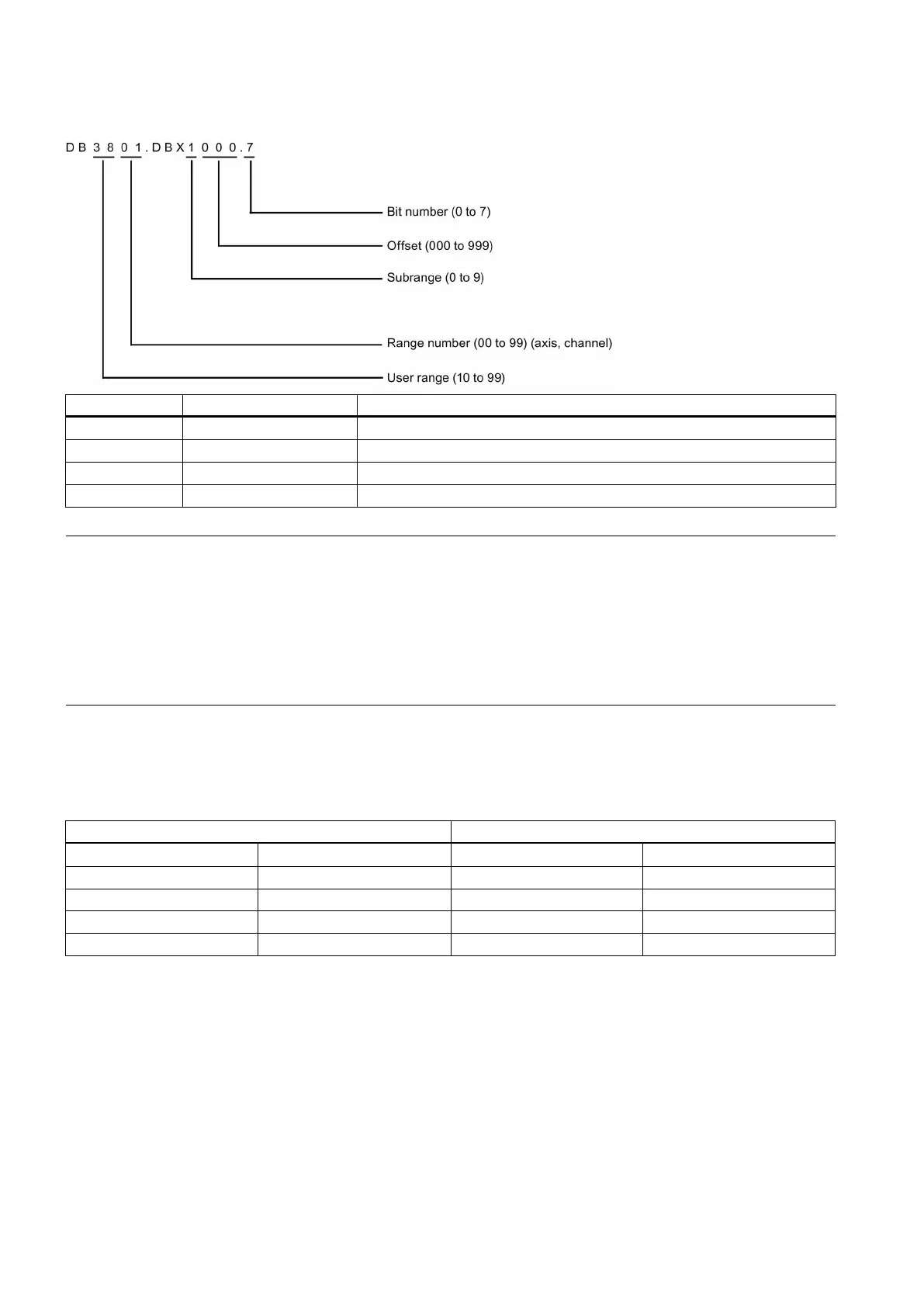
Structure of the DB-range address
Bit 7 of the byte with offset 0 in subrange 1 for axis 2, user range 38
Byte with offset 0 in subrange 0 for axis, user range 38
Work with offset 2 in subrange 0, range 0, user range 45
Double word with offset 4 in subrange 3, range 0, user range 25
Note
The permitted offset for an address depends on the access as follows:
Bit or byte access: any offset
Byte-size variables are placed one beside another seamlessly in a DB.
Word access: the offset must be divisible by 2.
Word-size variables (2 bytes) are always saved on straight offsets.
Double word access: the offset must be divisible by 4.
Double word-size variables (4 bytes) are always saved on offsets that are divisible by 4.
Notes on the PLC interface signal address representation
Currently, PLC interface signal addresses are represented by the V structure on the HMI while the manual shows them by
the DB structure.
See the following table for the relationship between the two representations.

 Loading...


