Commissioning Manual
01/2017
97
Note
You must install the Drive Bus terminator (that ships with the PPU) on X11 of the last servo drive; otherwise, the servo
system cannot work normally.
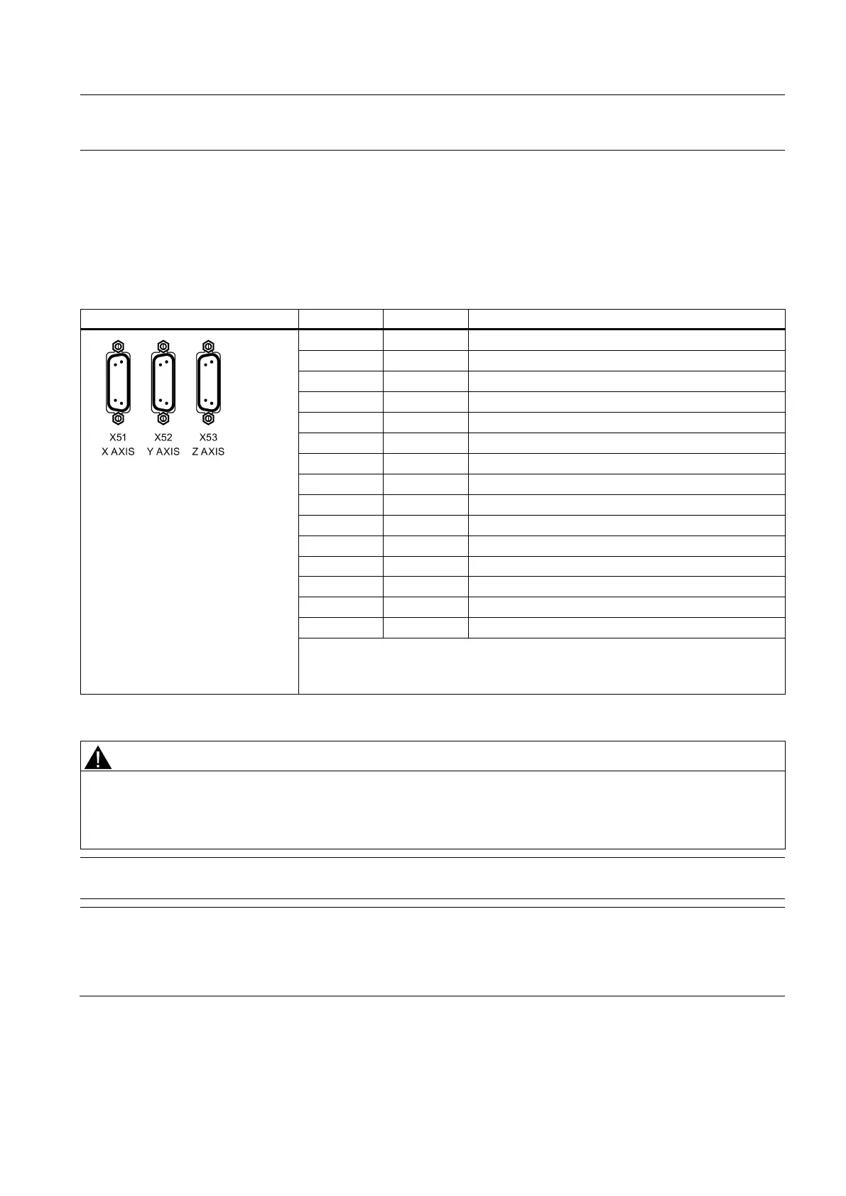
Pulse drive interfaces - X51, X52, X53 (PPU141.2 only)
Pin assignment
2 DIR+ DIRECTION, to drive side
4 BERO Zero mark, from drive side
POWER from the pin 1 of X200, +24 V output
ALARM RESET, to drive side
POWER from the pin 1 of X200, +24 V output
NEGATIVE PULSE, to drive side
NEGATIVE DIRECTION, to drive side
NEGATIVE ENABLE, to drive side
POWER from the pin 1 of X200, +24 V output
DRIVE READY, from drive side
The +24 V and M24 signals at the pulse drive interfaces can only be used when the
+24 V and M24 pins are connected at the interface X200.
Damage to controller or power supply
Pin 5, pin 8 or pin 12 of X51/52/53 are used for +24 V power output.
Incorrect connection of them will lead to damage to the CNC controller or the power supply.
Do not connect pin 5, pin 8 or pin 12 of X51/52/53 to ground.
Note
X51/52/53 does not support hot plugging.
Note
Filter
A line filter
(rated current: 16 A, degree of protection: IP20) is required so that the system can pass the CE certification
(radiated emission test or conducted emission test). The article number of Siemens recommended filter is 6SN1111-0AA01-
1BA1
.

 Loading...


