Commissioning Manual
256 01/2017
The first probe is connected to pin 4 (DI1) and the second probe to pin 5 (DI2) of interface X21. For the probe, use an
external voltage (24 V) whose reference potential should be connected to X21 pin 10
The following machine data should be checked and adjusted if necessary:
● MD13200[0] $MN_MEAS_PROBE_LOW_ACTIVE = 0 or 1
● MD13200[1] $MN_MEAS_PROBE_LOW_ACTIVE = 0 or 1
– Value 0 = deflected state 24 V (default)
– Value 1 = deflected state 0 V
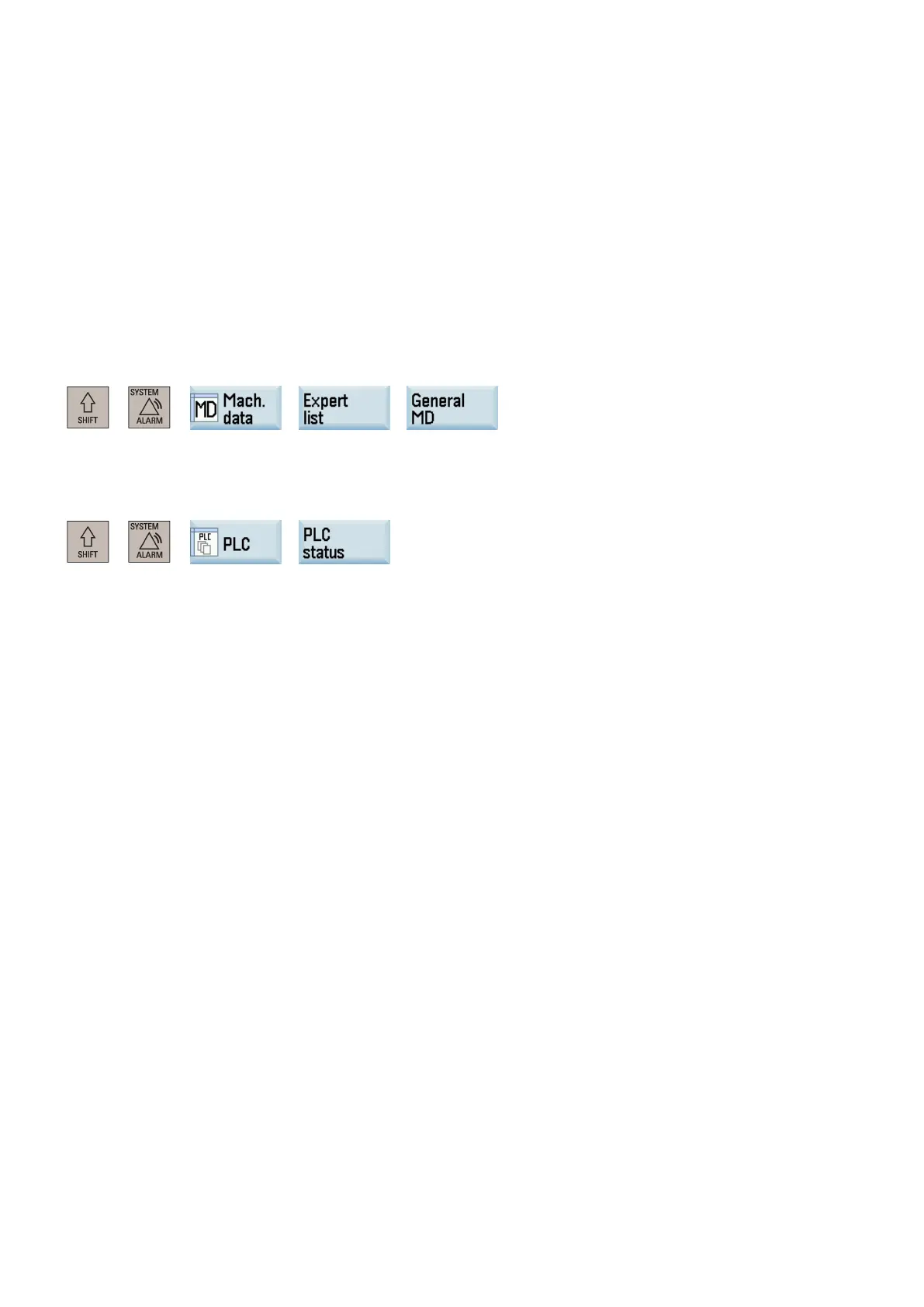
You can access this machine data through the following operations:
+ → → →
You can test the measuring signal by checking the PLC interface status through the following operations:
+ → →
Enter the interface address DB2700.DBB1 in the operand input field, and trigger the probe manually. In this case, the
corresponding PLC status bit changes, which indicates the probe is properly connected.
 Loading...


