9 – 24
Ground-fault tripping – G-tripping
If the trip unit is equipped with a ground-fault protection module,
loads can be protected against unpermissibly high ground-fault cur-
rents.
The trip unit ETU727 is equipped with a ground-fault protection
mod
ule as standard, whereas the trip units ETU745 - 776 can be
eq
uipped with it optionally.
q Ground-fault protection modules (page 9-68)
The pickup I
g
, together with the setting for the time-delay t
g
, deter-
mines the shutdown of ground-fault currents.
Some trip units can be switched over to an I
2
t-characteristic.. q
(page 9-27)
Neutral conductor protection - N-tripping
The trip units ETU727 ... 776 also make it possible to protect the
neutral conductor against overload. This requires a current trans-
former for the neutral conductor, which can be field installed. q
(page 9-117)
For tripping, the same long time delay t
R
applies as for overload trip-
ping.
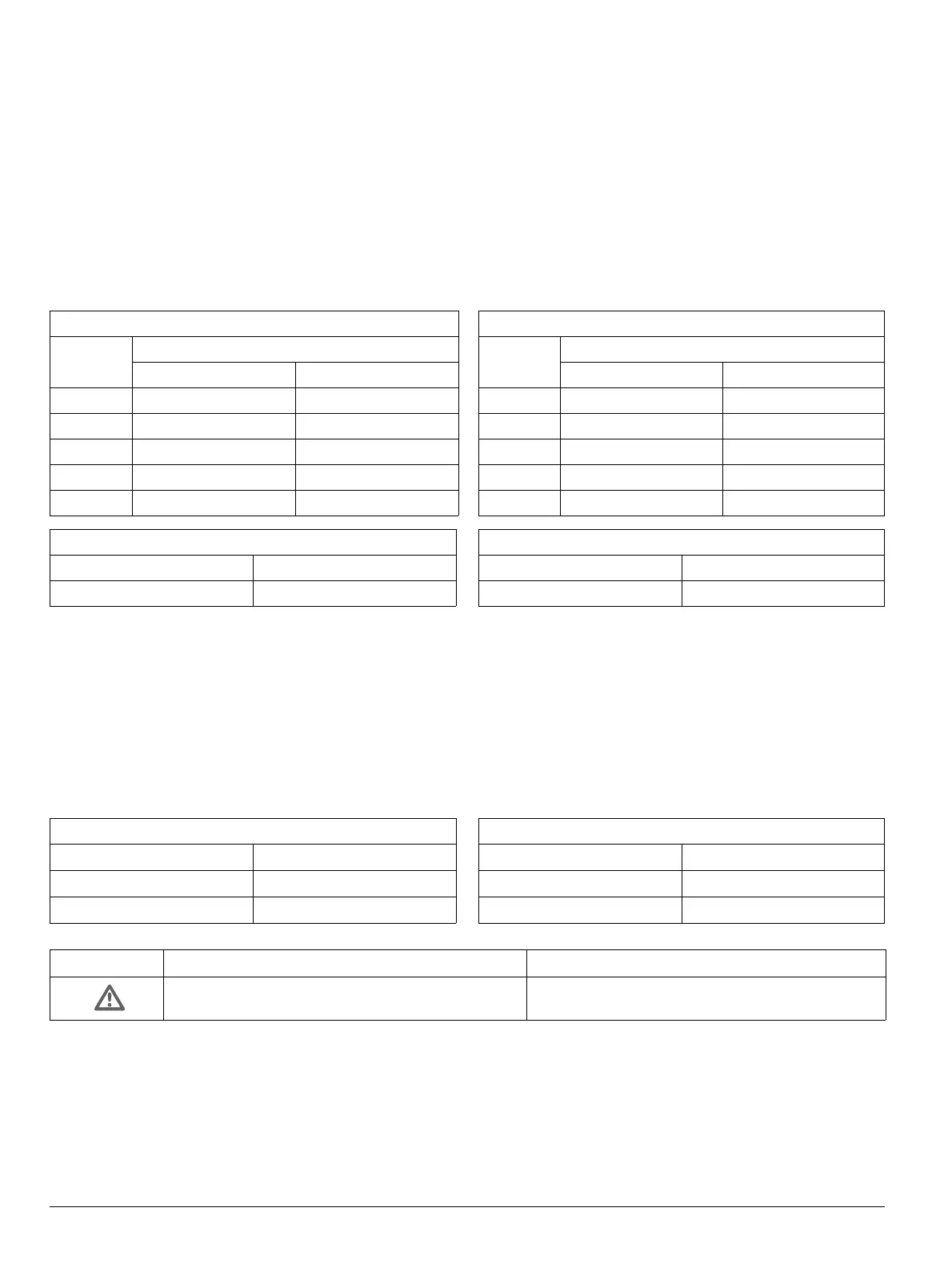
Current Settings for I
g
Frame size
I & II III
A 100 A 400 A
B 300 A 600 A
C 600 A 800 A
D 900 A 1000 A
E 1200 A 1200 A
Settings for t
g
ETU727 - 748 t
g
= 0.1 / 0.2 / 0.3 / 0.4 / 0.5 sec.
ETU755 - 776 t
g
= 0.1 - 0.5 sec.
Current Settings for I
N
ETU727
I
N
= I
n
; OFF
ETU745 - 748
I
N
= (0.5 / 1.0) × I
n
; OFF
ETU755 - 776
I
N
= (0.5 - 2.0) × I
n
; OFF
Erdschlussauslösung – G-Auslösung
Ist der Überstromauslöser mit einem Erdschlussschutzmodul aus-
gestattet, können Verbraucher vor unzulässig hohen Erdschluss-
strömen geschützt werden.
Der Überstromauslöser ETU727 verfügt standardmäßig über einen
Erds
chlussschutz, während die Überstromauslöser ETU745 - 776
opt
ional damit ausgerüstet werden können.
q Erdschlussschutzmodule (Seite 9-68)
Der Ansprechwert I
g
legt zusammen mit der Einstellung der Verzö-
gerungszeit t
g
die Abschaltung von Erdschlussfehlern fest.
Für einige Überstromauslöser besteht die Möglichkeit, auf eine
I
2
t-Charakteristik umzuschalten. q (Seite 9-27)
Neutralleiterschutz – N-Auslösung
Die Überstromauslöser ETU727 … 776 bieten die Möglichkeit, auch
den Neutralleiter vor Überlast zu schützen. Dazu ist ein Stromwand-
ler für den Neutralleiter erforderlich, der ggf. nachgerüstet werden
kann
. q (Seite 9-117)
Für die Auslösung gilt der gleiche Trägheitsgrad t
R
, wie für die Über-
lastauslösung.
Einstellwerte für I
g
Baugröße
I & II III
A 100 A 400 A
B 300 A 600 A
C 600 A 800 A
D 900 A 1000 A
E 1200 A 1200 A
Einstellwerte für t
g
ETU727 - 748 t
g
= 0,1 / 0,2 / 0,3 / 0,4 / 0,5 s
ETU755 - 776 t
g
= 0,1 - 0,5 s
Einstellwerte für I
N
ETU727
I
N
= I
n
; OFF
ETU745 - 748
I
N
= (0,5 / 1,0) × I
n
; OFF
ETU755 - 776
I
N
= (0,5 - 2,0) × I
n
; OFF
VORSICHT CAUTION
Einstellwerte I
N
> 1 x I
n
nur bei entsprechender
Dimensionierung des N-Leiters verwenden!
Setting I
N
> 1 x I
n
may be used only if the N-conduc-
tor has been designed to carry this current.
 Loading...


