8 – 1
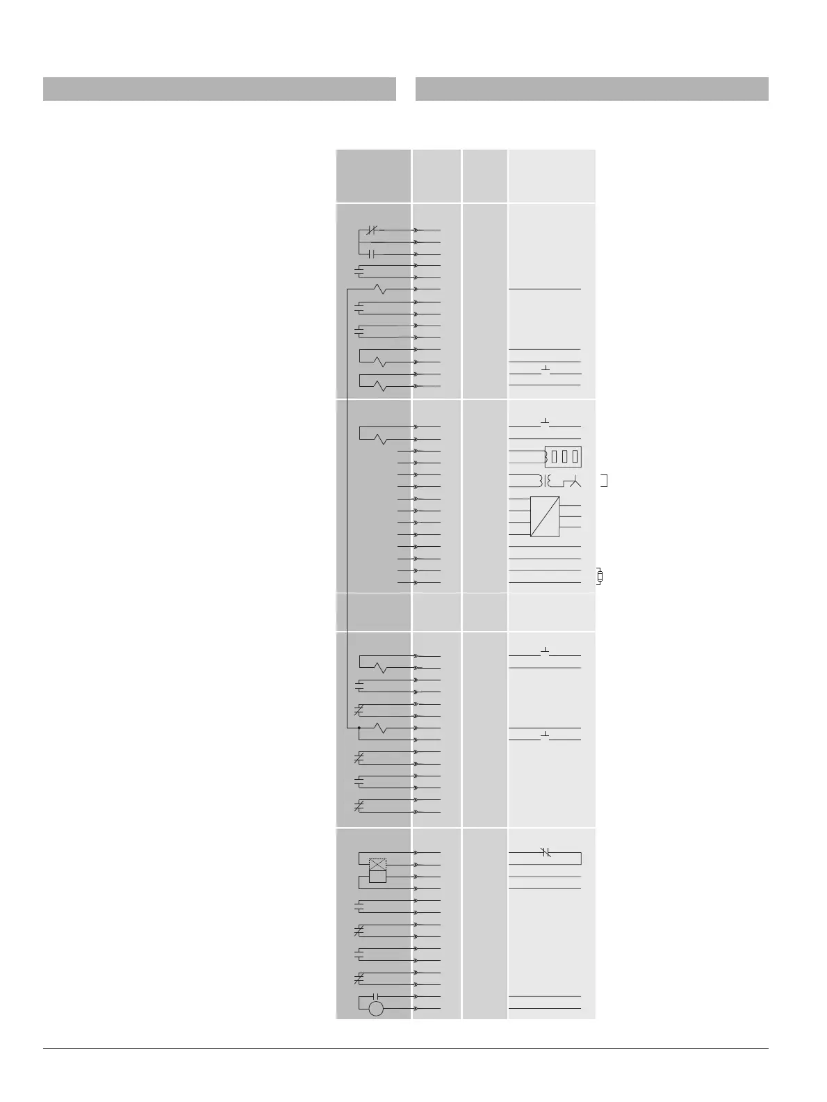
8 Schaltpläne
8.1 Klemmenbelegung
1
2
3
4
5
6
7
8
9
10
11
12
13
14
Fern-Rücksetzmagnet/Remote reset bell alarm & tripped indicator F7
CUB +
CUB -
24 V d.c.
0 V d.c.
G-Wandler/Ground Fault Sensor S1
G-Wandler/Ground Fault Sensor S2
N-Wandler
/Neutral Sensor S1
N-Wandler
/
Neutral Sensor S2
ExternerSpannungswandler/Externalvoltage transformer L1
ExternerSpannungswandler/Externalvoltage transformer L2
ExternerSpannungswandler/voltageExternal transformer L3
ExternerSpannungswandler Stern
/
Externalvoltage transformer Com
COM15/16, sonst nicht belegt
COM15/16, otherwise empty
1
2
3
4
5
6
7
8
9
10
11
12
13
14
S 2
S 2
Einschaltbereitschaftsmeldung/“Ready to close” signal S20
Einschaltmagnet
/
Closing Coil CC
S1
S1
1st Shunt Trip.
X8
X7
X6
X5
1
2
3
4
5
6
7
8
9
10
11
12
13
14
Charging motor (optional motor
cut-off switch shown in figure).
S 4
S 4
S 3
S 3
zweiter Hilfsauslöser: F3 “ ", F4 “ "UVR UVR td
2nd :auxiliary release F3 "UVR", F4 "UVR td"
nur F4 "Schnell-AUS"/F4 only “quick OPEN”
0053-07_nu
Intern
Internal
Extern
External
Klemmen
Terminals
ANSI
C37.2
device
#
LT / (+)
Control power
N / (-)
NOT-AUS oder Brücke
EMERGENCY OPEN
or short terminals
Phase A
Phase B
Phase C
24 V d.c. input
Abschlusswiderstand, 120 , 0.5 W
wenn kein externes CubicleBUS-Modul
O
Termination resistor if no
external CubicleBUS module connected
, 120 , 0.5 WO
Brücke, wenn kein N-Wandler
Short terminals, if no Neutral sensor
1
2
3
4
5
6
7
8
9
10
11
12
13
14
30
52CS
52CC
52CS
52TC
79
52TC / 86
52a
52b
52b
52b
52a
52a
52LC
52CC
52a
52b
52M
62
27
Meldeschalter am zweiten Hilfsauslöser
Signalling switch for 2nd shunt trip
Elektrisch "EIN"/Local electric
close S10
Meldeschalter am ersten Hilfsauslöser
Signalling switch for 1st shunt trip
Ausgelöst-Meldeschalter/Bell alarm signal switch
S24
Meldeschalter Fernauslösung
/Signallingswitch remote trip S26
Maglatch for remote trip kit F6
2. Hilfsauslöser
/2nd shunt trip F2
X9
LT / (+)
Control power
N / (-)
LT / (+)
Control power
N / (-)
LT / (+)
Control power
N / (-)
LT / (+)
LT / (+)
Control power
Control power
Fuse carriage FS III
N / (-)
X9.3
X9.4
LT / (+)
Control power
N / (-)
cc
OFLO
BA
TC
TC
CC
b
a
a
a
b
a
b
M
b
8 Circuit diagrams
8.1 Terminal assignment

 Loading...


