24 – 10
Der Zusammenbau erfolgt in umgekehrter Reihenfolge unter
Beachtung der angegebenen Anzugsmomente.
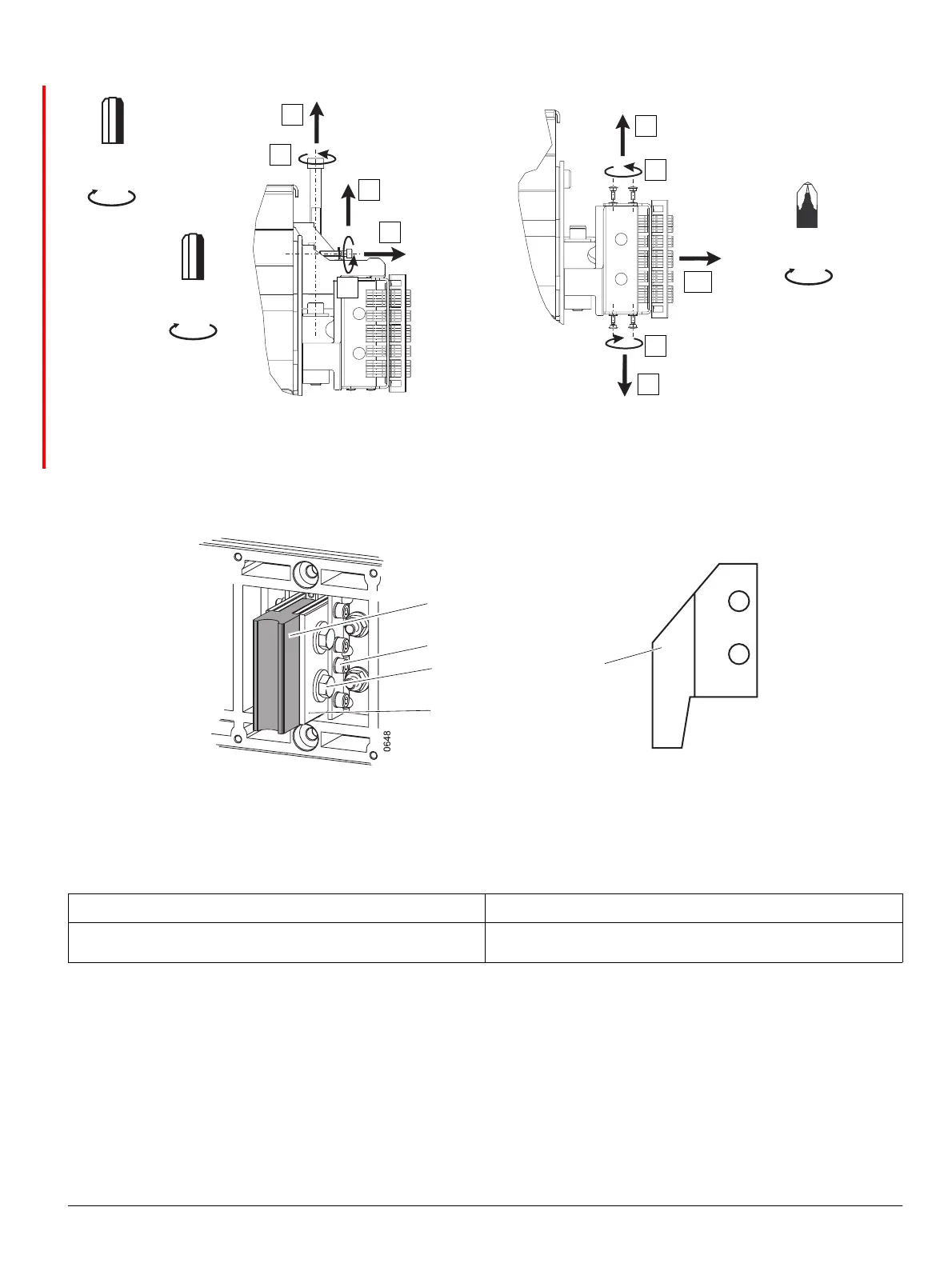
24.5.2 Messerkontakt wechseln
(1) Messerkontakt
(2) Zylinderschraube M6
(3) Sechskantschraube M12
(4) 4“ untere Anschlussschiene
(5) Messerkontakt für BG I oberer Anschluss
ACHTUNG NOTICE
Einbaulage des Messerkontaktes am oberen Anschluss für BG I
beachten!
Ensure correct orientation of FS I line stab tip when mounting.
0640-1
0640-2_nu
1
2
3
5
4
6
7
8
9
10
Gr. / Size
5
Gr. / Size
10
8 Nm
71 lb-in
40 Nm
28 ft-lb
PZ 2
3,2 Nm
28 lb-in
(1)
(2)
(3)
0728_nu
(5)
(4)
The reassembly is performed in reverse manner, with the given tor-
que values.
24.5.2 Exchanging the stab tip
(1) Stab tip
(2) Cheese-head screw M6
(3) Hexagon bolt M12
(4) 4“ runback load side
(5) Stab tip for FS I line side

 Loading...


