Y AXIS SENSOR REPLACEMENT (FRONT PANEL SENSOR)
1) turn off the machine and disconnect from the power supply.
2) gain access to the top compartment (Ch. 7.3).
3) gain access to the bottom compartment (Ch. 7.4).
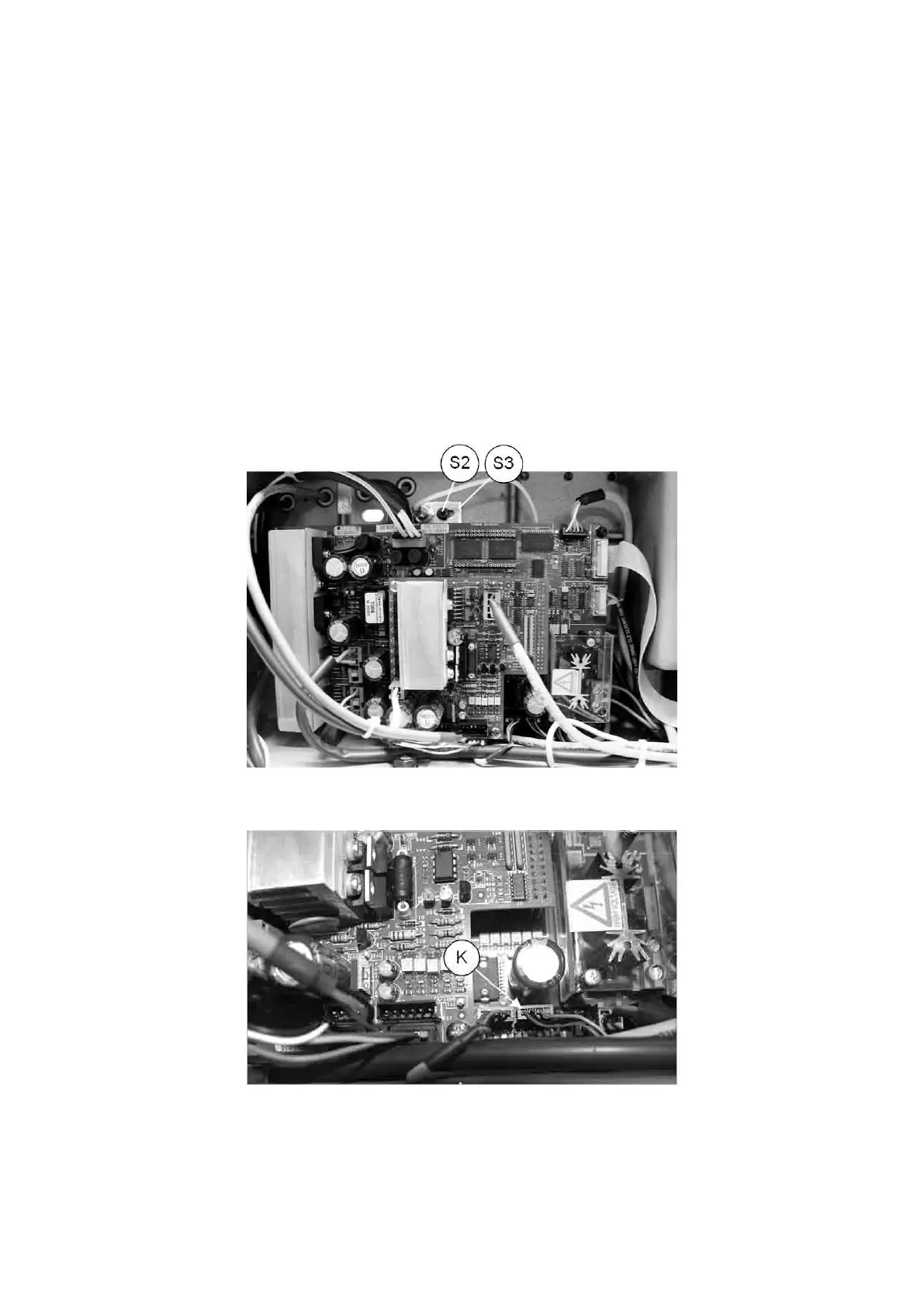
4) use pliers to disconnect the Y axis sensor connection (K) from the board.
5) loosen the screw (S2) and remove together with the sensor and its support (S3). Remove the worn sensor and
replace with a new one.
Fit the support with the new sensor, regulating it until it almost touches the upper bracket
(Fig. 93).
6) securing the nut (K1)
7) connect the sensor connector (K).
8) proceed to Maintenance > Machine zeroes (Ch. 5.8.2 ).
9) replace the bottom plate.
10) turn the machine upright, place the top cover in position and secure with the 4 screws (U2) (Ch. 7.3).
Fig. 91
Fig. 92
Operating Manual UC199
Copyright Silca 2012
81