5.8.3 OPTIONAL LOADER UNIT
NOTE: the screen shows different information according to whether there is a Loader Unit (optional)
or not.
Pointer on 3 - press ENTER; the display will show:
WITH STANDARD 4 SIDED CLAMPS:
INSTALLATION
LOADER UNIT
Press [START]
to proceed
INSTALLATION
LOADER UNIT
Positioning
In progress !
INSTALLATION
LOADER
Turn off the machine
andttheloaderunit.
ATTENTION: itiscompulsorytoturnoffthemachinebeforettingtheLoaderUnitorpart
of it.
Proceed as follows:
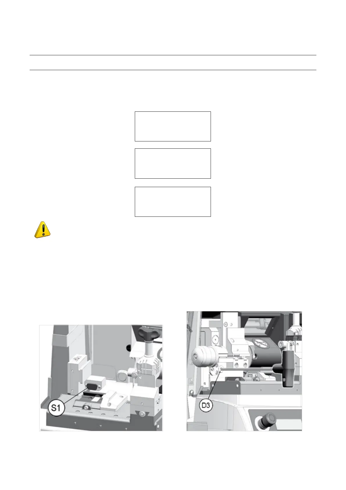
1) Remove the Standard cutting Clamp: Loosen the screw (D2) and pull out the clamp to the left.
2) Fit the Loader: remove the cover/protection (S1) on the serial outlet located in the loader seat. Please keep
the protection for future use. Insert the loader and push all the way in then tighten the screw (D3) using the
(long) hex wrench provided.
3) Fit the Automatic Clamp: the automatic clamp into the special dovetail runner, pushing all the way in to the
right, then tighten the screw (D2) (Fig. 68).
Fig. 65 Fig. 66
Operating Manual UC199
Copyright Silca 2012
58