7.14 LAMP REPLACEMENT
1) turn off the machine and disconnect from the power supply.
2) gain access to the top compartment (Ch. 7.3 .
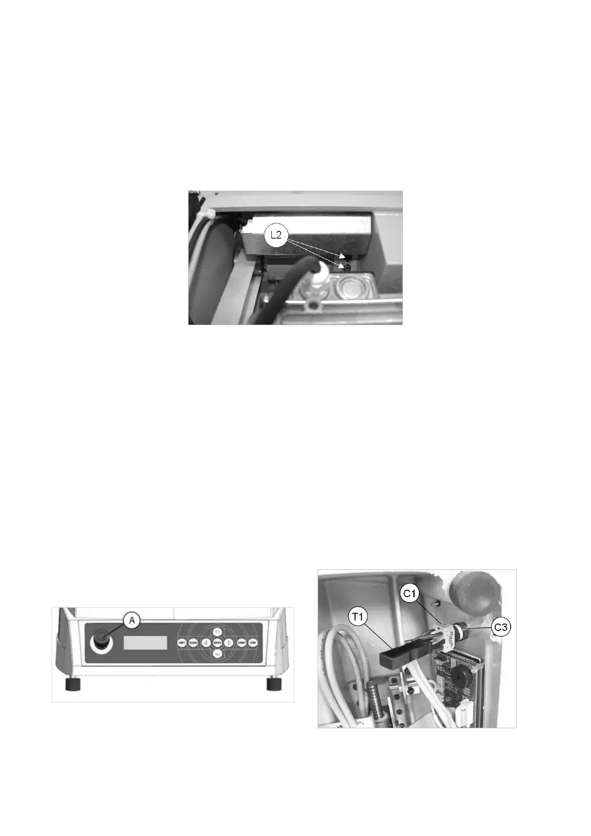
3) loosenthe2lampxingscrews(L2)(Fig.98).
4) remove the light bulb taking care not to use pointed utensils for this operation.
5) insert the new light bulb.
6) secure the lamp by tightening the 2 screws (L2).
Fig. 98
7.15 MASTER/EMERGENCY SWITCH REPLACEMENT
1) turn off the machine and disconnect from the power supply.
2) gain access to the bottom compartment (Ch. 7.4).
3) insert the special utensil provided (T1) into the slit on the terminal strip in order to detach it from the switch
(Fig. 99).
4) loosen the ring nut (C3) in order to remove the faulty push button/switch.
5) tthenewpushbutton/switchandsecurebytighteningtheringnut(C3).
6) in order to remove the wiring from the switch/push button, eliminate any wiring clips, disconnect the wires from
the 6 terminal board connectors (5-6-7-8-9-10), from the 2 connections (R3) to the power input and loosen the
2earthingwirexingnuts(M1)and(C2)(Fig.87).
7) toxthenewwiring,repeattheoperationsdescribedabove,inreverseorder.
8) connect the switch/push button terminal strip to the switch.
9) repeat the above operations in reverse order to gain access to the bottom compartment.
Fig. 99 Fig. 100
Operating Manual UC199
Copyright Silca 2012
85